Setup elements, Board settings dip switch, Setup elements –22 – Altera 100G Development Kit, Stratix IV GT Edition User Manual
Page 30: Board settings dip switch –22
2–22
Chapter 2: Board Components
Configuration, Status, and Setup Elements
100G Development Kit, Stratix IV GT Edition Reference Manual
September 2010
Altera Corporation
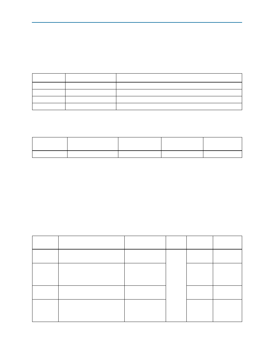
Board references S10-S12 are push-button switches for MAX II+Flash FPP
configuration. Use the PGM_SEL (S10) push-button to select the configuration
programming image stored in the flash memory.
lists the push-button switches references, names, and functional
descriptions.
lists the push-button switches component references and the
manufacturing information.
Setup Elements
The development board includes the board settings DIP switch as part of the setup
elements.
Board settings DIP switch
The development board includes a board settings DIP switch which controls various
features specific to the board and the MAX
II CPLD EPM2210 System Controller logic
design.
lists the board settings DIP switch controls and descriptions.
Table 2–10. Push-Button Switches
Board Reference
Push-Button Switch Name
Description
S9
CPU_RESETn
Reset signal for the FPGA.
S10
PGM_SEL
Selects between two .pof files (factory or user) stored in the flash.
S11
LOAD
Initiates loading of the FPGA.
S12
FACTORY
Initiates loading of factory design into the FPGA.
Table 2–11. Push-Button Switches Component References and Manufacturing Information
Board Reference
Device Description
Manufacturer
Manufacturer
Part Number
Manufacturer
Website
S9–S12
Push-Button switches
Panasonic Corporation
EVQPAC07K
Table 2–12. Board Settings DIP Switch Controls
Board
Reference
Description
Schematic Signal
Name
I/O
Standard
Other
Connections
Settings
SW2.1
Disables the embedded USB-Blaster.
USB_DISABLEn
2.5-V
U80.H2
1: Enabled
0: Disabled
SW2.2
Selects SMA or PLL for the
differential clock that goes to the
global clock inputs of clock A tree
structure.
DIFFCLKA_SEL
U19.3
1: PLL input
0: SMA input
SW2.3
Selects SMA or PLL that goes to the
transceivers of clock A tree structure.
REFCLKA_SEL
U15.3
1: PLL input
0: SMA input
SW2.4
Selects SMA or PLL for the
single-ended clock that goes to the
global clock inputs of clock A tree
structure.
SE_CLKA_SEL
U14.3
1: SMA input
0: PLL input