Power measurement, Power measurement –67 – Altera 100G Development Kit, Stratix IV GT Edition User Manual
Page 75
Chapter 2: Board Components
2–67
Power
September 2010
Altera Corporation
100G Development Kit, Stratix IV GT Edition Reference Manual
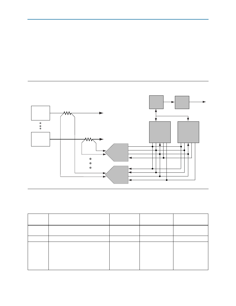
Power Measurement
There are 12 power supply rails which have on-board voltage and current sense
capabilities. These 8-channel differential 24-bit ADC devices and rails are split from
the primary supply plane by a low-value sense resistor for the ADC to measure
voltage and current. A serial peripheral interface (SPI) bus connects these ADC
devices to the MAX II CPLD EPM2210 System Controller as well as the Stratix IV GT
FPGA.
shows the block diagram for the power measurement circuitry.
lists the development board power components and its manufacturing
information.
Figure 2–13. Power Measurement Circuitry
SCK
DSI
DSO
CSn
8 Ch.
To Plane 0x0
To Plane 0xE
Supply
0x0
Supply
0xE
R
SENSE
R
SENSE
SCK
DSI
DSO
CSn
8 Ch.
MAX II CPLD
Stratix IV GT
LTC2418
LTC2418
U52
EPM
240
USB
PHY
To User PC
Power GUI
JTAG Chain
SPI Bus
Embedded
USB-Blaster
U51
Table 2–44. Development Board Power Components (Part 1 of 2)
Reference
Designator
Device Description
Manufacturer
Manufacturer
Part Number
Manufacturer
Website
J1
Right angle PC mount DC power jack
3-pin connector
Switchcraft, Inc.
RAPC712X
SW1
Slide switch
E-Switch, Inc.
EG2201A
U25, U26,
U27, U35,
U40, U42,
U43, U45,
U60, U68,
U69, U86
1.5-A low input voltage VLDO linear
regulator (1.14 V–5.5 V V
IN
, 0.4 V–2.6 V
V
OUT
)
Linear Technology
LTC3026EDD#PBF