Status elements, Status leds, Status elements –20 – Altera 100G Development Kit, Stratix IV GT Edition User Manual
Page 28: Status leds –20
2–20
Chapter 2: Board Components
Configuration, Status, and Setup Elements
100G Development Kit, Stratix IV GT Edition Reference Manual
September 2010
Altera Corporation
Status Elements
The development board includes board-specific status LEDs and switches for
enabling and configuring various features on the board, as well as a 16 character × 2
line LCD for displaying board power and temperature measurements. This section
describes these status and setup elements.
Status LEDs
Surface mount LEDs indicate the various status of the board. A logic 0 is driven on the
I/O port to turn the LED on while a logic 1 is driven to turn the LED off.
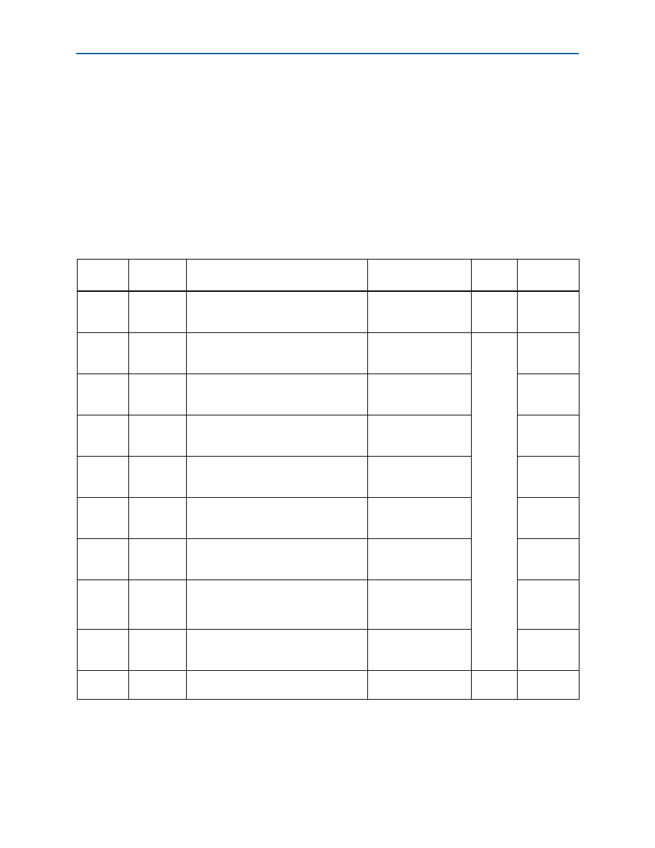
Table 2–7
lists the LED board references, names, and functional descriptions.
Table 2–7. Status LEDs
Board
Reference
LED Name
LED Description
Schematic
Signal Name
I/O
Standard
Other
Connections
D7
Power
Blue LED. Illuminates when the board
power switch (SW1) is on. Driven by the
3.3-V regulator.
—
—
—
D12
DUPLEX
Green LED. Illuminates to indicate Ethernet
full duplex status. Driven by the Marvell
88E1111 PHY.
ENET_LED_DUPLEX
2.5-V
CMOS
U66.60,
U66.70
D13
1000
Green LED. Illuminates to indicate Ethernet
linked at 1000-Mbps connection speed.
Driven by the Marvell 88E1111 PHY.
ENET_LED_LINK1000
U66.73,
U44.AU35
D14
100
Green LED. Illuminates to indicate Ethernet
linked at 100-Mbps connection speed.
Driven by the Marvell 88E1111 PHY.
ENET_LED_LINK100
U66.74,
U44.AU35
D15
10
Green LED. Illuminates to indicate Ethernet
linked at 10-Mbps connection speed.
Driven by the Marvell 88E1111 PHY.
ENET_LED_LINK10
U66.64,
U66.76
D16
TX
Green LED. Blinks to indicate Ethernet PHY
transmit activity. Driven by the Marvell
88E1111 PHY.
ENET_LED_TX
U66.68,
U66.61
D17
RX
Green LED. Blinks to indicate Ethernet PHY
receive activity. Driven by the Marvell
88E1111 PHY.
ENET_LED_RX
U66.69,
U66.65
D19,
D20,
D25
User
Green LED. Illuminates when the user .pof
image is successfully programmed into the
FPGA.
USER1_POF
USER2_POF
USER3_POF
U72.N3
U72.N5
U72.N2
D26
Factory
Green LED. Illuminates when the factory
.pof image is successfully programmed
into the FPGA.
FACTORY_POF
U72.M4
D27
USB
Green LED. Blinks to indicate the
embedded USB-Blaster activity.
USB_LED
3.3-V
CMOS
U80.L1