Altera 100G Development Kit, Stratix IV GT Edition User Manual
Page 51
Chapter 2: Board Components
2–43
Components and Interfaces
September 2010
Altera Corporation
100G Development Kit, Stratix IV GT Edition Reference Manual
J37.97
Receive XCVR pair 6 to FPGA
CFP_RX_P6
1.2-V PCML
P2
—
J37.98
Receive XCVR pair 6 to FPGA
CFP_RX_N6
P1
—
J37.100
Receive XCVR pair 7 to FPGA
CFP_RX_P7
M2
—
J37.101
Receive XCVR pair 7 to FPGA
CFP_RX_N7
M1
—
J37.103
Receive XCVR pair 8 to FPGA
CFP_RX_P8
K2
—
J37.104
Receive XCVR pair 8 to FPGA
CFP_RX_N8
K1
—
J37.106
Receive XCVR pair 9 to FPGA
CFP_RX_P9
H2
—
J37.107
Receive XCVR pair 9 to FPGA
CFP_RX_N9
H1
—
J37.41
Global alarm.
0: Alarm on in MDIO alarm register
1: Alarm off
CFP_GLB_ALRM
H9
—
J37.48
Management data clock
CFP_T_MDC
H8
—
J37.47
Management data I/O (bi-directional
data)
CFP_T_MDIO
H7
—
J37.38
Module absent.
0: Module present. Pull-up resistor
on the host
1 or NC: Module absent
CFP_MOD_ABS
L10
—
J37.37
Module low-power mode.
0: Power-on enabled
1 or NC: Module in low-power (safe)
mode
CFP_MOD_LOPWR
J9
—
J37.39
Module reset.
0: Reset
1 or NC: Module enabled. Pull-down
resistor on the module
CFP_MOD_RST
M12
—
J37.33
Programmable alarm 1 set via MDIO
and MSA for RXS, RX CDR lock
indication.
0: Locked
1: Unlocked
CFP_PRG_ALRM1
N10
—
J37.34
Programmable alarm 2 set via MDIO
and MSA (HIPWR_ON).
0: Module not powered-up
1: Module power-up completed
CFP_PRG_ALRM2
M10
—
J37.35
Programmable alarm 3 set via MDIO
and MSA for module initialization
(MOD_READY)
0: Initialization not done
1: Initialization completed
CFP_PRG_ALRM3
F7
—
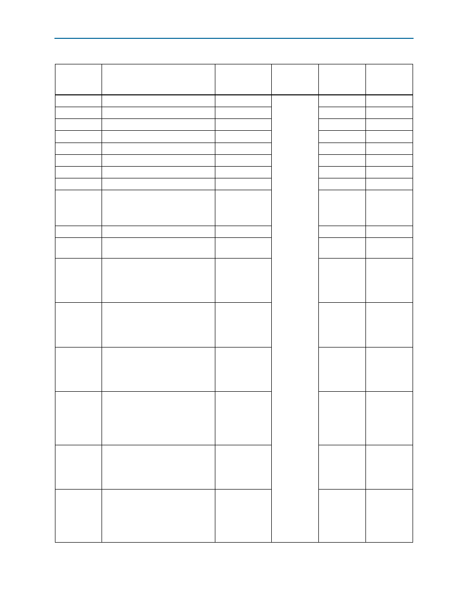
Table 2–33. CFP Interface Pin Assignments, Schematic Signal Names, and Functions (Part 2 of 3)
Board
Reference
Description
Schematic
Signal Name
i/O Standard
Stratix IV GT
Device
Pin Name
Other
Connections