4 analogue output/rs 232 socket – Casella CEL Software for the Microdust dust monitor User Manual
Page 11
Options that are not currently available are marked X; for example while
the instrument is logging data, calibration cannot be performed.
Pressing
several times at any point provides a short cut back to the Main
menu.
The Main menu contains all parameters and options relevant to operation and
gives access to three sub-menus.
Calibration menu
Allows the instrument to be calibrated.
Configuration menu
Allows the instrument parameters to be
specified.
Logger
Allows the logger to be configured and
data storage to be started and stopped.
1.4
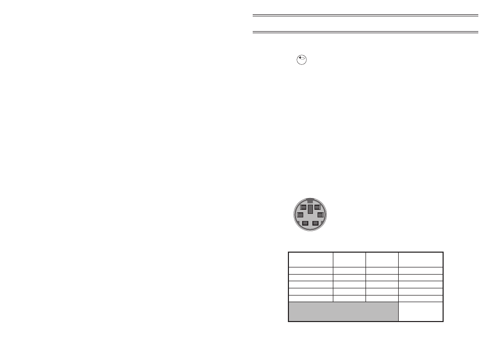
Analogue Output/RS 232 Socket
An analogue output signal is available for interfacing the MicroDust pro to a
chart recorder or external data logger. Wiring details of the analogue output/
RS 232 socket are shown in Figure 5 and Table 1.
From firmware Version 06, the user can select the output to represent either
average or raw data sources, or set a high or low alarm condition.
Esc
Figure 5:
Line identities of the Analogue/RS 232
socket, viewed externally (i.e. also from
the solder bucket side of the plug)
00018
6
4
2
5
3
1
Table 1: Line functions
Function
Pin Number Wire Colour
9-way D Type
(PC RS 232)
Analogue ground
1
Yellow
N/A
Analogue Out
2
Red
N/A
RS 232 Receive in
3
White
3 (TX out)
RS 232 Transmit out
4
Black
2 (RX in)
Comms ground
5
Blue
5 (Ground)
4 (DTR), 8 (CTS), 6
(DSR)
Linked together
Page 11 of 60
Description
MICRODUST pro Aerosol Monitoring System &
WINDUST pro Application Software - Handbook