Leds cirlamp manager has 11 indicator leds – CIRCUTOR CIRLAMP Series User Manual
Page 14
Advertising
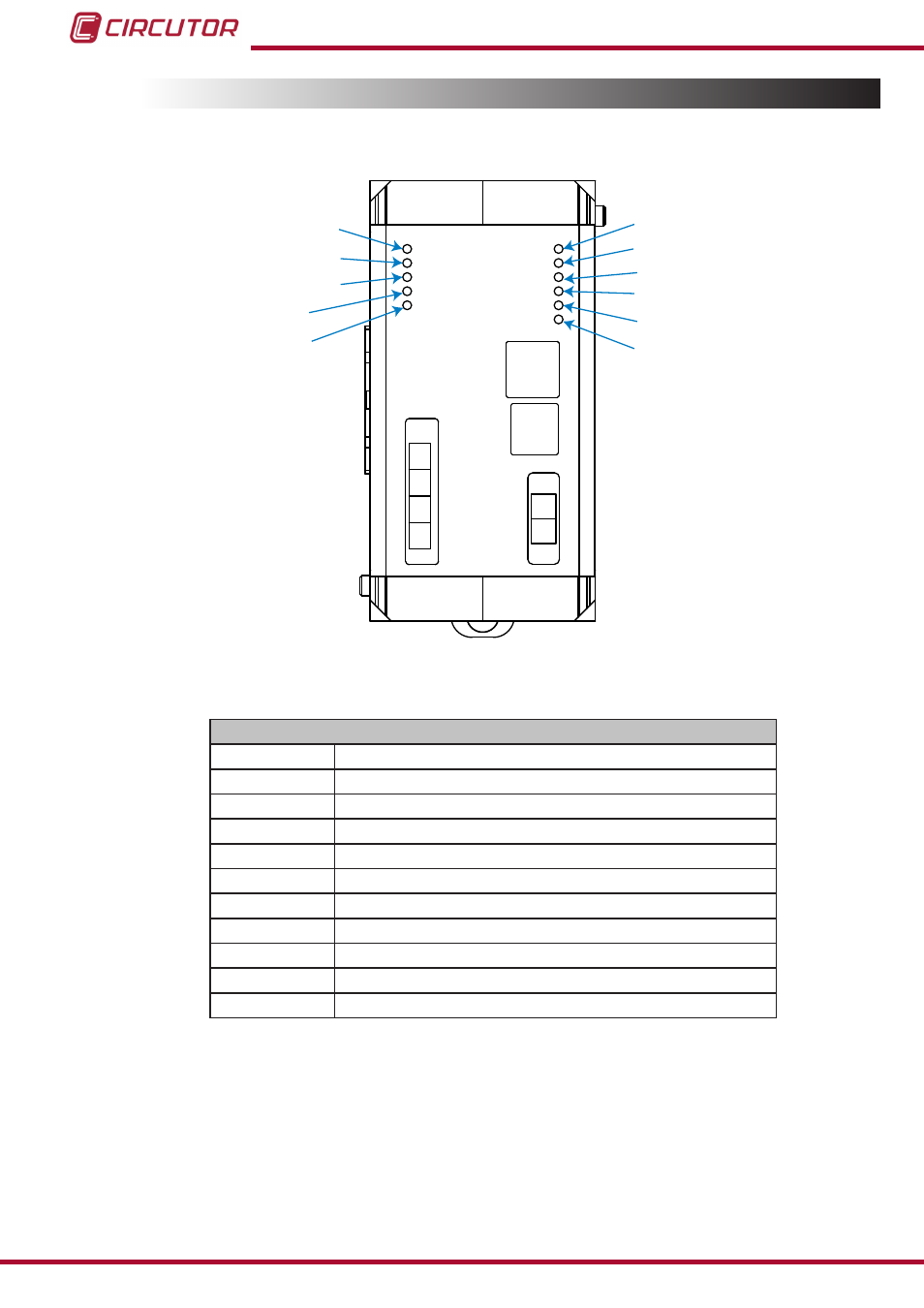
4.2.- LEDs
CirLAMP Manager has 11 indicator LEDs.
N
L
L1
L2
L3
N
ETHERNET
PLC POWER
PLC >> CPU
PLC << CPU
TX PLC
RX PLC
CPU POWER
ACTIVITY
ALARM
PLC.DATA
ETH.LINK
ETH.ACT.
PLC POWER
PLC >> CPU
PLC << CPU
TX PLC
RX PLC
CPU POWER
ACTIVITY
ALARM
PLC DATA
ETH.LINK
ETH.ACT.
Figure 6: CirLAMP Manager LEDs�
Table 3:List of CirLAMP Manager LEDs�
LEDs
PLC POWER Part of the connected PLC.
PLC>>CPU
Communication from the PLC to the
CirLAMP Manager.
PLC<<CPU
Communication from the
CirLAMP Manager to the PLC.
TX PLC
Sending frames.
RX PLC
Receiving frames.
CPU POWER CirLAMP Manager connected.
ACTIVITY
The unit is performing a task.
ALARM
An alarm has been activated.
PLC DATA
Receiving frames.
ETH�LINK
The Ethernet port is connected.
ETH�ACT
Ethernet port activity.
14
CirLAMP system
Instruction Manual
Advertising