Figure 91 – CIRCUTOR CIRLAMP Series User Manual
Page 83
Advertising
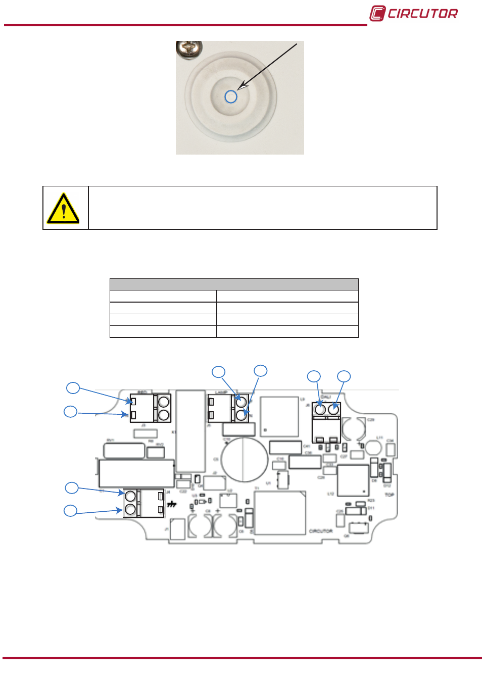
Figure 91:gland terminals
�
Do not power the unit on until it has been completely closed.
7�1�3� UNIT TERMINALS
Table 87:List of terminals for the CirLAMP DALI
Unit terminals
1: L, Phase input
5: L, Output relay : ON/OFF control relay
2: N, Neutral input
6: N, Output relay : ON/OFF control relay
3: Earthing, Earthing input
7:-, DALI communications
4: Earthing, Earthing output
8:+, DALI communications
J3
J4
J5
J6
1
2
3
4
5
6
7
8
Figure 92:Terminals for CirLAMP Node DALI�
83
Instruction Manual
CirLAMP system
Advertising