CIRCUTOR CIRLAMP Series User Manual
Page 73
5�- CirLAMP Node DN
5.1.- INSTALLATION OF THE UNIT
5�1�1� PRELIMINARY RECOMMENDATIONS
“4.1.1. PRELIMINARY RECOMMENDATIONS”.
5�1�2� INSTALLATION
Terminals, opening covers or removing elements can expose parts that are
hazardous to the touch while the unit is powered. Do not use the unit until it is
fully installed.
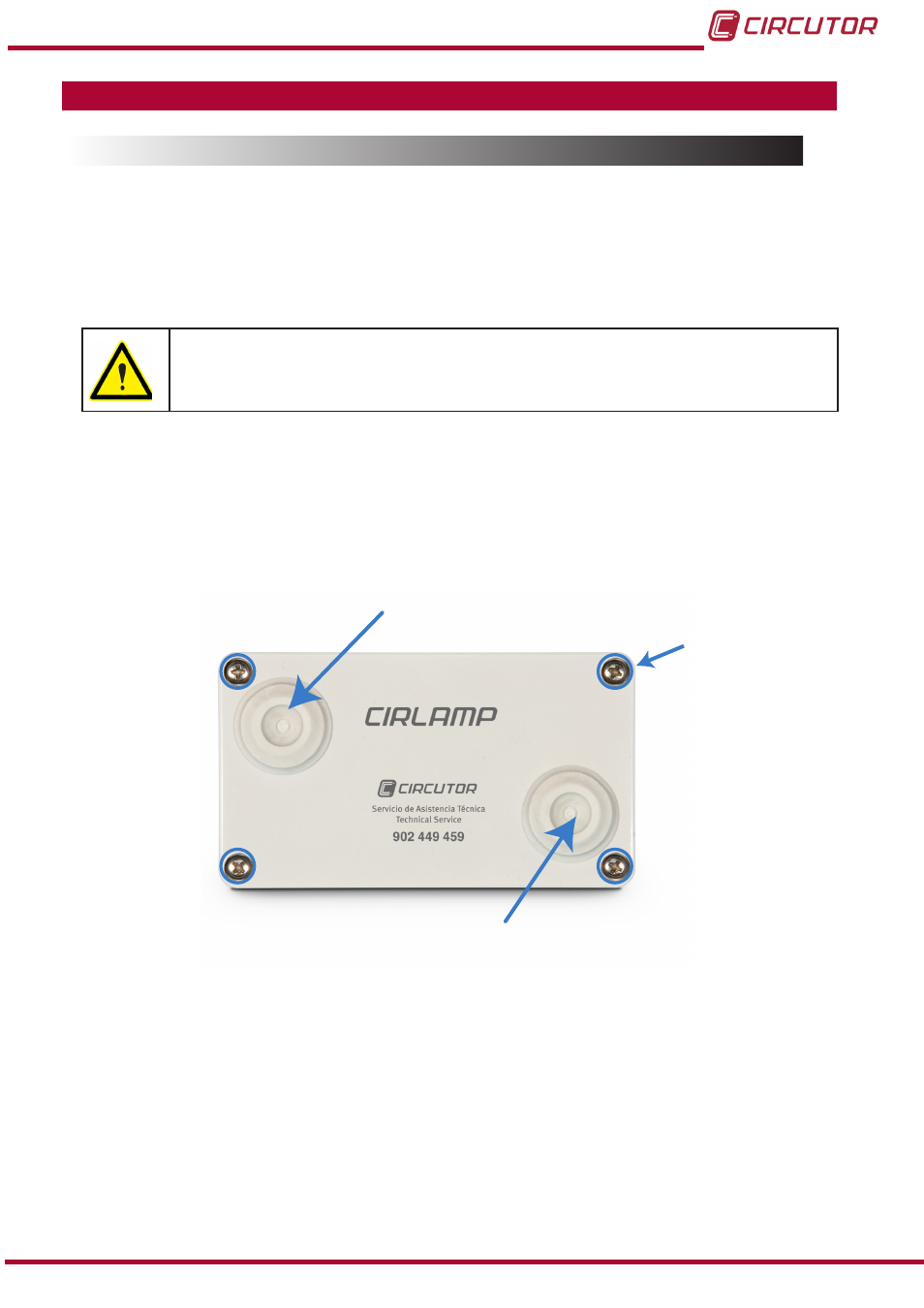
The unit has two cable seal/gland terminals (
):
Input for the power supply cables.
Output towards the lamp and output for the bi-level ballast.
The unit must be opened to complete the installation; to do this unscrew the four front screws.
Entrada alimentación
Input for power supply cables
Salida hacia la lámpara
Output towards the light
Tornillo
Screw
Figure 80:Position of the CirLAMP Node cable seal terminals and screws
�
Connect the unit with 5 x 2.5 mm
2
hoses.
To pass the hoses through the cable seal terminals, which guarantees the IP65 protection de-
gree of the unit, you need to pierce the cable seal from outside of the box with a 3 mm
2
punch
73
Instruction Manual
CirLAMP system