CIRCUTOR CIRLAMP Series User Manual
Page 75
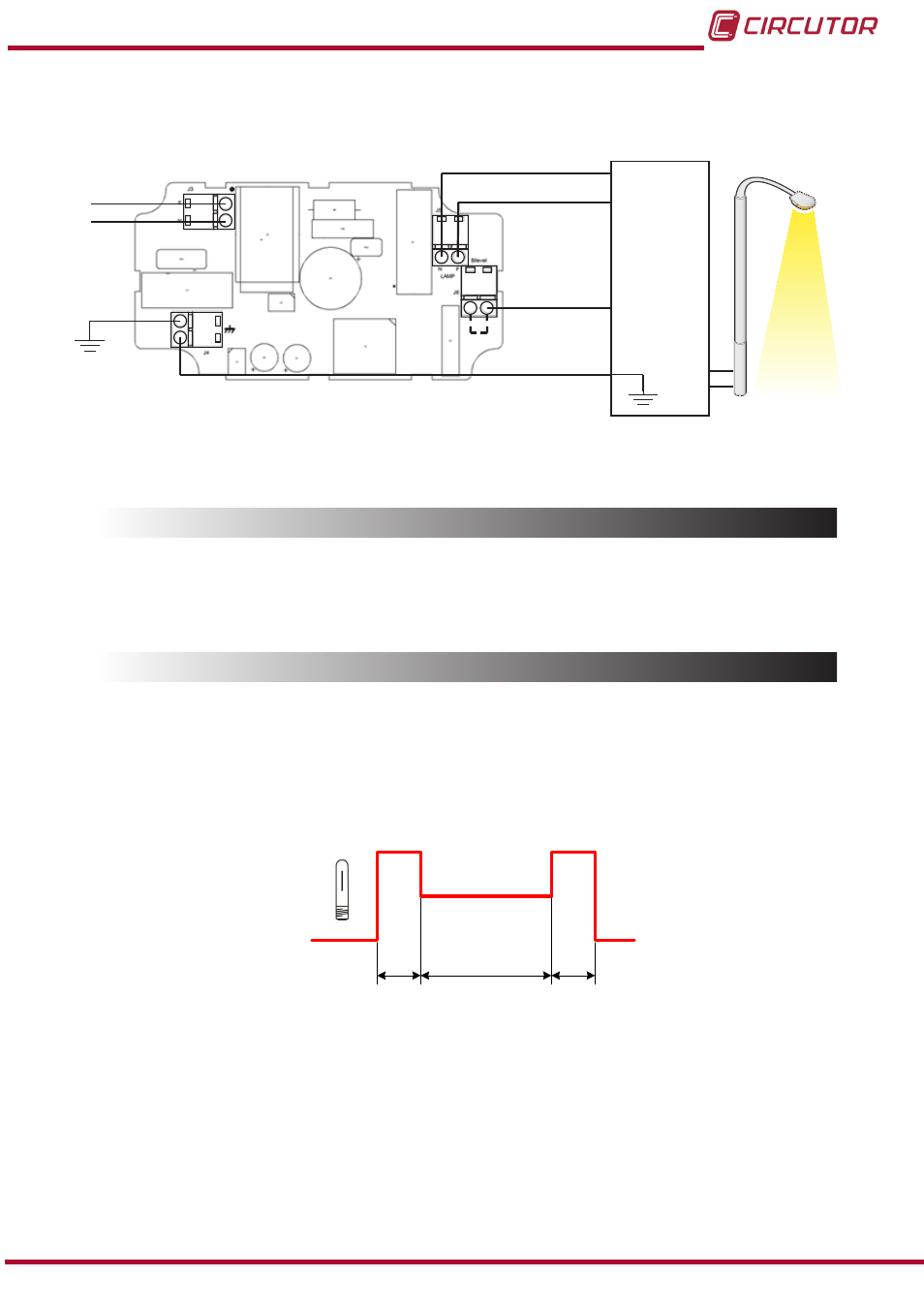
5�1�4� CONNECTION DIAGRAM
J3
J4
J5
J6
L
N
L
L
N
N
Control
Doble nivel
Balasto
Alimentación
Power supply
Ballast
2-level
control
*
*
Conectado internamente
Internally connected
Figure 83:CirLAMP Node DN connection diagram�
5.2.- CONNECTION WITH CirLAMP MANAGER
The connection with the
CirLAMP Manager is performed via the electrical network using PLC
technology. (see
5.3.- OPERATION
5�3�1� WORK INTERVALS
The
CirLAMP Node DN connects to a bi-level ballast or driver, where two different work inter-
vals can be defined.
Each work interval is defined by the value of the outlet power and the interval time period.
T1
T2
T3
100%
50%
0%
Figure 84:Operation of a bi-level ballast�
shows an example of operation with a bi-level ballast or driver:
On powering, the unit begins to work delivering 100% of the power to the lamp during the de-
fined time T1.
After this time, it enters interval T2, where 50% of the power is sent to the lamp.
After T2, the output once again feeds 100% of the power, during a defined time, T3. After time
T3 has elapsed, the primary cutoff relay opens and the lamp is switched off.
75
Instruction Manual
CirLAMP system