CIRCUTOR CIRLAMP Series User Manual
Page 84
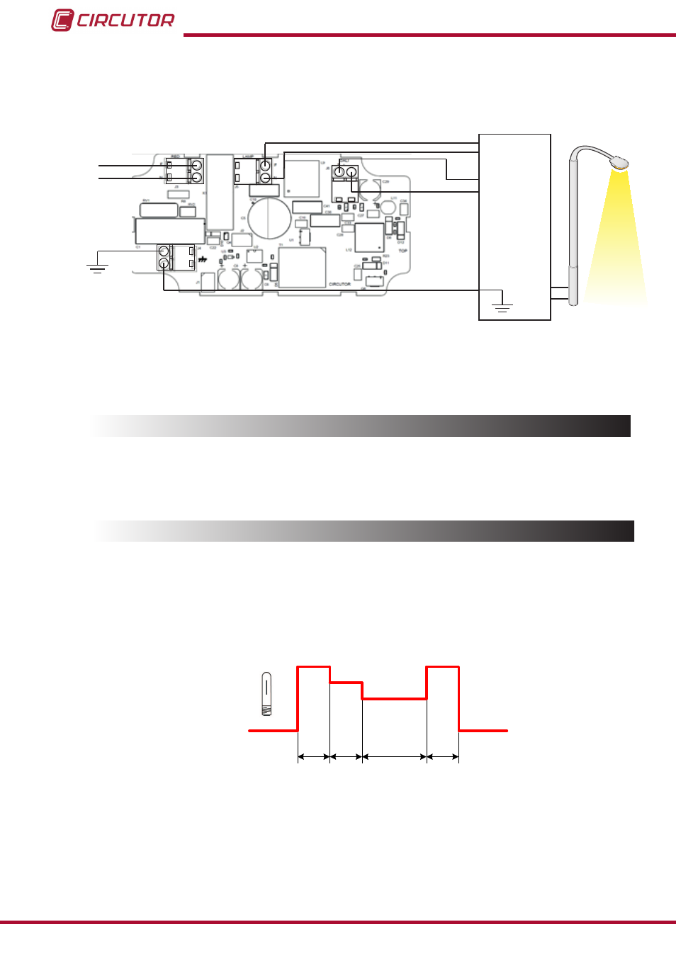
7�1�4� CONNECTION DIAGRAM
L
N
N
N
L
L
Control
DALI
Balasto
Alimentación
Power supply
Ballast
DALI
control
- DA
+ DA
- DA
+ DA
J4
J3
J5
J6
Figure 93:Connection diagram CirLAMP Node DALI
7.2.- CONNECTION WITH CirLAMP MANAGER
The connection with the
CirLAMP Manager is performed via the electrical network using PLC
technology. (see
“4.3.- PLC”)
7.3.- OPERATION
7�3�1� WORK INTERVALS
The
CirLAMP Node DALI connects to a ballast with input control DALI, where four different
work intervals can be defined.
Each work interval is defined by a command of DALI control.
T1
T2
T3
T4
100%
75%
50%
0%
Figure 94:Operation of a DALI ballast�
shows an example of operation with a DALI ballast:
On powering, the unit begins to work delivering 100% of the power to the lamp during the de-
fined time T1.
Once this time has elapsed, interval T2 begins, where the power fed to the lamp is reduced to
75%, applying the corresponding command to the DALI ballast.
84
CirLAMP system
Instruction Manual