Figure 86 – CIRCUTOR CIRLAMP Series User Manual
Page 79
Advertising
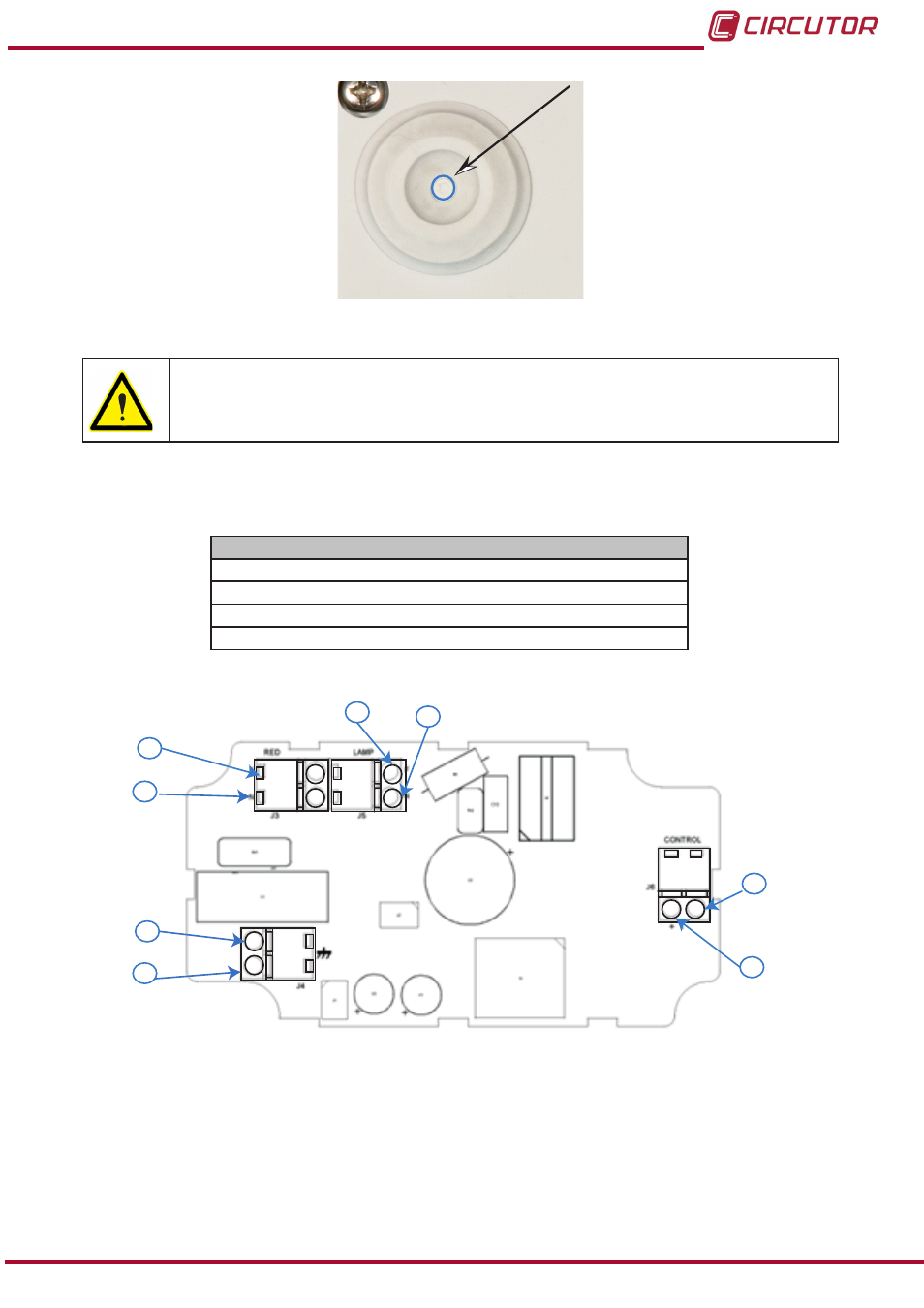
Figure 86:gland terminals
�
Do not power the unit on until it has been completely closed.
6�1�3� UNIT TERMINALS
Table 86:List of terminals for the CirLAMP Node 1���10V�
Unit terminals
1: L, Phase input
5: L, Ballast phase
2: N, Neutral input
6: N, Ballast neutral
3: Earthing, Earthing input
7:-, 1 to 10V output
4: Earthing, Earthing output
8:+, 1 to 10V output
J3
J4
J5
J6
1
2
3
4
5
6
7
8
Figure 87:Terminals for CirLAMP Node 1 ��� 10V�
79
Instruction Manual
CirLAMP system
Advertising