Leprecon Litescape dimmer User Manual
Page 20
Litescape User’s Manual, Page 4
Testing an Output Channel
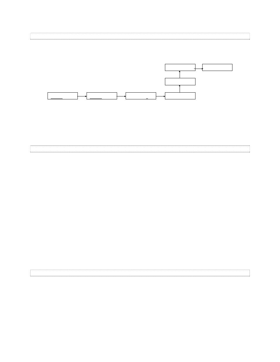
To activate the channel test feature, navigate to the CHANNEL CURVE sub menu for channel 1 using the
NEXT and PREVious buttons. Now press UP twice to put channel 1 into the “force-to-on” state. The “on”
field should be inverse blinking, indicating that the change has not yet been accepted.
MAIN MENU
dimmers scenes
ENTER
V
SELECT DIMMER:
dimmer1 dimmer2
DIMMER ADDRESS
dimmer1 1 >
ENTER
V
ENTER
V
UP
UP
NEXT
EV
CHAN: 1 2 3
CURVE:st st st
CHAN: 1 2 3
CURVE:
nd
st st
CHAN: 1 2 3
CURVE:
on
st st
CHAN: 1 2 3
CURVE:
on
st st
Testing an Output Channel
Press
ENTER to put channel 1 in the on state. If the system is properly wired, the lamp load connected to
LWD-2400 physical channel 1 will be full-on.
Before proceeding, be sure to put channel 1 back into
st, or standard curve mode.
Attaching and Using DMX
DMX data is not required for the dimmer to operate properly. However, if DMX control is desired, each
dimmer must receive the DMX data stream directly. DMX data is
not transferred over the panel
communication (BRDTalk) network.
On the bottom of the unit is a 5 pin XLR connector for DMX in. This connector is provided as a convenient
connection for testing, as permanent wiring is usually connected to the internal terminal strip.
The correct connection for the DMX input are shown in Figure 2. DMX is usually connected to a control
console via a single 5 pin XLR connector. The pin designations shown match the pin-out of the XLR
connector; Pin 1 = Gnd, Pin 2 = Data-, Pin 3 = Data+
Once a DMX source has been connected; either to the internal strip or the external XLR connector, verify
that movement of faders 1 through 12 corresponds to light output on LWD channels 1 through 12. If DMX
control is unsuccessful, the following may aid in locating the problem:
•
check STATUS menu – DMX status
•
check LWD-2400 “dimmer1” DMX base address, should be set to “1” (see “Setting the DMX Base
Address” above)
•
try a different cable
•
check console for 1:1 patching
•
do a full-on test of the output channel (see “Testing an Output Channel” above).
•
attach the console to another, known good dimmer and verify operation
DMX Termination
The last dimmer in the DMX wiring chain should be terminated. To terminate the DMX input of the LWD-
2400, locate jumper JP300 on the LWD processor board. The jumper shunt must be moved to the right
side position, next to the silkscreen legend ‘DMX Term’.
Other dimmers in the system should not be terminated, with JP300 in the left side position.