Hapter, Hysical, Nstallation – Leprecon Litescape dimmer User Manual
Page 27
QuickStart Procedures—Physical Installation
Litescape User’s Manual, Page 11
C
HAPTER
4: P
HYSICAL
I
NSTALLATION
How to Assign Wall Panels to a Room
1
Set the Houselites Enabled switch to enabled on all LWD-2400 dimmers in the system. Locate the 8-
position DIP switch on the inside of the front door of the LWD-2400 on the main circuit board. Move
switch #6, the 3
rd
from the top, to the right to enable Houselites. Power off the LWD-2400 and restart
it to complete the change.
2
Locate the room switch on the reverse side of the wall panel. It is a small square rotary switch. It is
labeled ROOM to distinguish it from the similar PANEL switch near it.
3
Use a small flat-blade screwdriver to set the room switch until the indicator points at the assigned
room number, which must be from 1 to 8.
4
Locate the panel switch near the room switch. Set the switch as described in step 3 to assign a
unique panel number between 1 and 12 (A=10, B=11, C=12). This is important when there are two or
more wall panels in one room. If two wall panels in one room have the same panel number,
unpredictable results will occur.
5
To disable a wall panel, set its panel switch to 13, 14 or 15 (D, E or F on the switch).
How to Connect a Houselite System for networked operation
1
Use commercial CAT5 cable only.
2
Use point-to-point runs only. Each dimmer and panel must connect to only two other network nodes.
Tees or junction blocks will create data errors, and result in unreliable operation. Keep total length
under 1,000 feet within one Houselite system.
3
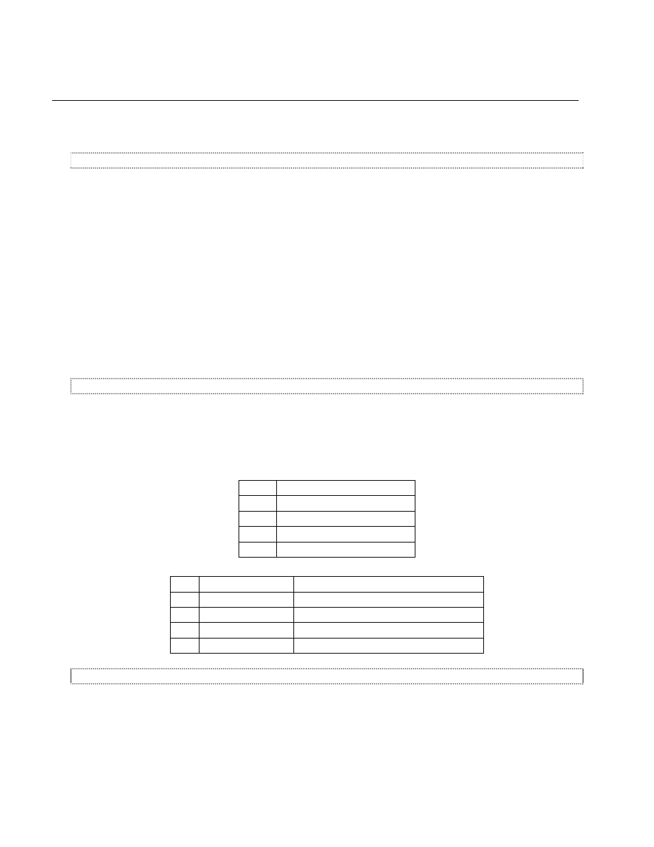
Connect the wires to devices according to the tables below.
pair
CAT 5 Colors
1
orange—orange/white
2
brown—brown/white
3
green—green/white
4
blue—blue/white
pin
Description
LWD Lightscape Color(s)
1
V + connection
Blue, green, brown
2
Data, or COM -
Orange/white
3
Data, or COM +
Orange
4
V – connection
blue/white, green/white, brown/white
How and Where to Terminate Devices in the Houselite System
1
Termination is required at the two endpoints of the daisy-chain network. The endpoint can be either a
dimmer or a panel, depending on the routing of the network cable.
2
To terminate the LWD-2400: The termination jumper is JP301, located on the left center of the PCB,
on the inside of the unit’s front door. Pin 1 is at the top. Place the shorting jumper to connect Pin 1
and Pin 2.