Lynx Studio E44 User Manual
Page 26
26
will appear here, with an E22 four record channels will appear.
Input names are abbreviated so that they can appear in 4 spaces. Sources that start with “A”
are for Analog and with “D” are for Digital. For instance, “AIn4” means Analog Input 4,
“DI2L” means Digital In 2 Left (Note: digital inputs have a stereo orientation, analog have a
mono orientation).
Clicking the Input Source button generates a menu with all of the Analog and Digital Inputs
available to choose from. For the vast majority of users the default configuration is ideal and
would never be changed. There are a few reasons why assigning inputs other than the
defaults may be beneficial:
•
Assigning the same physical input (i.e. Analog In 1+2) to multiple Record devices
can allow the user to record the same signal into two different programs or onto
two different tracks within the same program.
•
If the Digital Inputs are being used primarily and not the Analog Inputs, it can be
useful to assign the first record devices to the Digital Inputs instead of Analog, so
that they appear first in the list. For an E44 user, it may be advantageous to have
the Analog and Digital inputs appear in contiguous pairs, rather than the default
arrangement of the four Analogs First and then the four Digitals.
When an input source button shows a Digital Input, the button will be Green when that Input
is locked to a valid digital signal, or it will appear as Red when no clock signal is present.
w
Pan Pot
The Pan Pot knob controls the pan position of the input as it is being monitored through an
output. IT HAS NO EFFECT ON THE RECORDED SIGNAL. It is only pertinent to
monitoring.
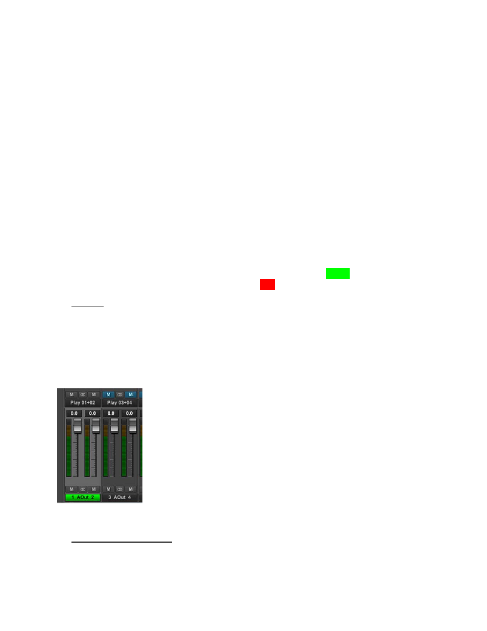
Hardware based, no latency input monitoring is implemented by clicking on a physical
output button at the bottom of the mixer screen. For instance, in the screen picture below,
Analog Out 1 and 2 have been selected (Output selection is always done with stereo pairs):
The Output label appearing in green indicates that this is the Selected
Output. A different Output can be selected by clicking a different
pair’s Output button. In this state, any of the Sources in the Input
Section can be routed to this output. For instance, if we have an input
signal on Analog In 3, and we wish to hear it through Analog Out
1+2, Select Analog Out 1+2 in the bottom of the Outputs Section,
then un-mute Analog In 3 in the Inputs Section. Now signals from
Analog Input 3 will be heard through Analog Output 1. If we would
like to hear the signal through Analog Outputs 1+2 both, then the Pan
Knob can be used to pan Analog In 3 to the center, or anywhere
within the stereo spectrum.
By default, Odd number inputs are panned to the left, and Even number to the right.
e
Numeric Level Indicator
This displays the amount of attenuation performed on the associated record source. This is
attenuation for the Monitor level of the signal; it has NO bearing on the level being recorded