Is-is nsr configuration example, Network requirements, Configuration procedure – H3C Technologies H3C S5560 Series Switches User Manual
Page 195: Verifying the configuration
179
Total number of interfaces: 1
Number of waiting LSPs: 0
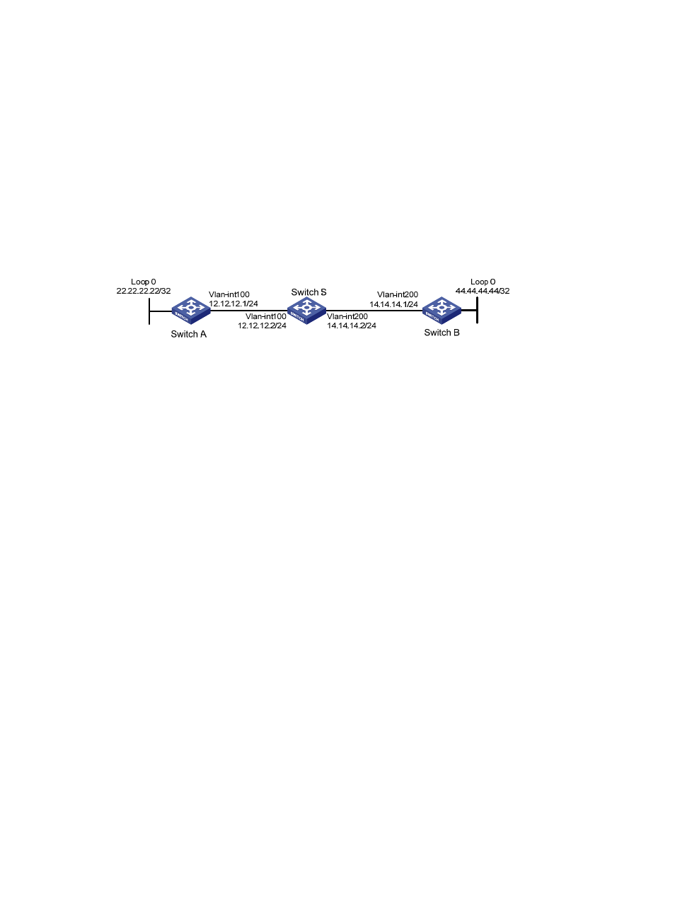
IS-IS NSR configuration example
Network requirements
As shown in
, Switch S, Switch A, and Switch B belong to the same IS-IS routing domain.
•
Run IS-IS on all the switches to interconnect them with each other.
•
Enable IS-IS NSR on Switch S to ensure forwarding continuity between Switch A and Switch B when
an active/standby switchover occurs on Switch S.
Figure 45 Network diagram
Configuration procedure
1.
Configure the IP addresses and subnet masks for interfaces on the switches. (Details not shown.)
2.
Configure IS-IS on the switches to make sure Switch S, Switch A, and Switch B can communicate
with each other at Layer 3 and dynamic route update can be implemented among them with IS-IS.
(Details not shown.)
3.
Enable IS-IS NSR on Switch S.
<SwitchS> system-view
[SwitchS] isis 1
[SwitchS-isis-1] non-stop-routing
[SwitchS-isis-1] return
Verifying the configuration
# Reoptimize process placement on Switch S to trigger an active/standby switchover.
<SwitchS> system-view
[SwitchS] placement reoptimize
Predicted changes to the placement
Program Current location New location
---------------------------------------------------------------------
syslog 0/0 0/0
diagusageratio 0/0 0/0
l3vpn 0/0 0/0
fc 0/0 0/0
dns 0/0 0/0
lauth 0/0 0/0
aaa 0/0 0/0
lsm 0/0 0/0
rm 0/0 0/0
rm6 0/0 0/0
track 0/0 0/0