Configuration procedure – H3C Technologies H3C S5560 Series Switches User Manual
Page 303
287
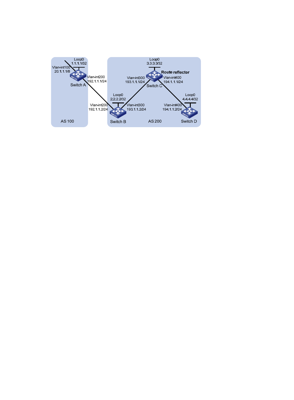
Configure Switch C as a route reflector with clients Switch B and Switch D to allow Switch D to learn route
20.0.0.0/8 from Switch C.
Figure 68 Network diagram
Configuration procedure
1.
Configure IP addresses for interfaces and configure OSPF in AS 200. (Details not shown.)
2.
Configure BGP connections:
# Configure Switch A.
<SwitchA> system-view
[SwitchA] bgp 100
[SwitchA-bgp] router-id 1.1.1.1
[SwitchA-bgp] peer 192.1.1.2 as-number 200
[SwitchA-bgp] address-family ipv4 unicast
[SwitchA-bgp-ipv4] peer 192.1.1.2 enable
# Inject network 20.0.0.0/8 to the BGP routing table.
[SwitchA-bgp-ipv4] network 20.0.0.0
[SwitchA-bgp-ipv4] quit
[SwitchA-bgp] quit
# Configure Switch B.
<SwitchB> system-view
[SwitchB] bgp 200
[SwitchB-bgp] router-id 2.2.2.2
[SwitchB-bgp] peer 192.1.1.1 as-number 100
[SwitchB-bgp] peer 193.1.1.1 as-number 200
[SwitchB-bgp] address-family ipv4 unicast
[SwitchB-bgp-ipv4] peer 192.1.1.1 enable
[SwitchB-bgp-ipv4] peer 193.1.1.1 enable
[SwitchB-bgp-ipv4] peer 193.1.1.1 next-hop-local
[SwitchB-bgp-ipv4] quit
[SwitchB-bgp] quit
# Configure Switch C.
<SwitchC> system-view
[SwitchC] bgp 200
[SwitchC-bgp] router-id 3.3.3.3
[SwitchC-bgp] peer 193.1.1.2 as-number 200
[SwitchC-bgp] peer 194.1.1.2 as-number 200