Configuration procedure – H3C Technologies H3C S5560 Series Switches User Manual
Page 314
298
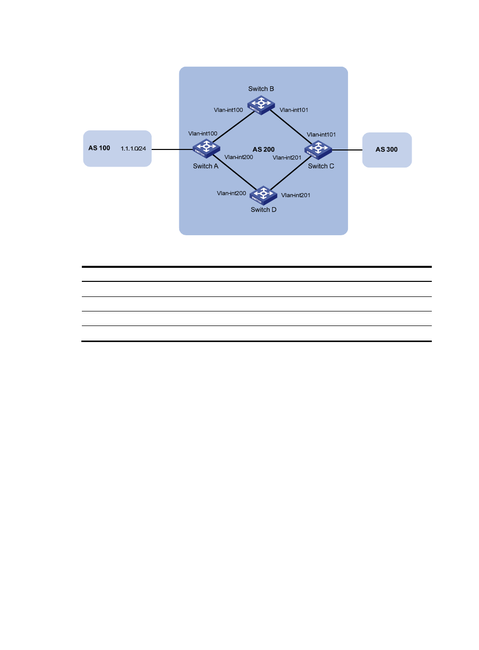
Figure 72 Network diagram
Table 17 Interface and IP address assignment
Device Interface
IP
address
Device
Interface IP
address
Switch A
Vlan-int100
3.0.1.1/24
Switch C
Vlan-int101
3.0.2.2/24
Vlan-int200
2.0.1.1/24
Vlan-int201
2.0.2.2/24
Switch B
Vlan-int100
3.0.1.2/24
Switch D
Vlan-int200
2.0.1.2/24
Vlan-int101
3.0.2.1/24
Vlan-int201
2.0.2.1/24
Configuration procedure
1.
Configure IP addresses for interfaces. (Details not shown.)
2.
Configure OSPF to make sure that Switch A and Switch C are reachable to each other. (Details not
shown.)
3.
Configure BGP on Switch A:
# Establish two IBGP connections to Switch C.
<SwitchA> system-view
[SwitchA] bgp 200
[SwitchA-bgp] peer 3.0.2.2 as-number 200
[SwitchA-bgp] peer 2.0.2.2 as-number 200
[SwitchA-bgp] address-family ipv4 unicast
[SwitchA-bgp-ipv4] peer 3.0.2.2 enable
[SwitchA-bgp-ipv4] peer 2.0.2.2 enable
[SwitchA-bgp-ipv4] quit
[SwitchA-bgp] quit
# Create ACL 2000 to permit 1.1.1.0/24 to pass.
[SwitchA] acl number 2000
[SwitchA-acl-basic-2000] rule permit source 1.1.1.0 0.0.0.255
[SwitchA-acl-basic-2000] quit