Network requirements – H3C Technologies H3C S5560 Series Switches User Manual
Page 67
51
[SwitchD] display ip routing-table
Destinations : 12 Routes : 12
Destination/Mask Proto Pre Cost NextHop Interface
0.0.0.0/32 Direct 0 0 127.0.0.1 InLoop0
10.0.0.0/8 RIP 100 1 11.3.1.1 Vlan300
11.3.1.0/24 Direct 0 0 11.3.1.2 Vlan300
11.3.1.0/32 Direct 0 0 11.3.1.2 Vlan300
11.3.1.2/32 Direct 0 0 127.0.0.1 InLoop0
11.4.1.0/24 Direct 0 0 11.4.1.2 Vlan400
11.4.1.0/32 Direct 0 0 11.4.1.2 Vlan400
11.4.1.2/32 Direct 0 0 127.0.0.1 InLoop0
127.0.0.0/8 Direct 0 0 127.0.0.1 InLoop0
127.0.0.0/32 Direct 0 0 127.0.0.1 InLoop0
127.0.0.1/32 Direct 0 0 127.0.0.1 InLoop0
127.255.255.255/32 Direct 0 0 127.0.0.1 InLoop0
BFD for RIP configuration example (single-hop echo detection
for a directly connected neighbor)
Network requirements
As shown in
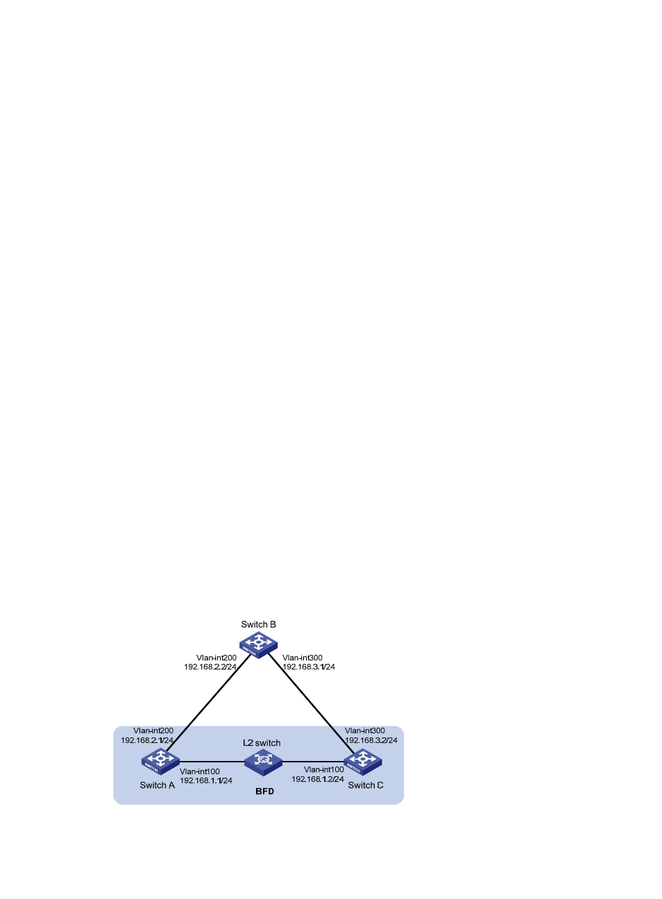
, VLAN-interface 100 of Switch A and Switch C runs RIP process 1. VLAN-interface
200 of Switch A runs RIP process 2. VLAN-interface 300 of Switch C and VLAN-interface 200 and
VLAN-interface 300 of Switch B run RIP process 1.
•
Configure a static route destined for 100.1.1.1/24 and enable static route redistribution into RIP on
Switch C. This allows Switch A to learn two routes destined for 100.1.1.1/24 through VLAN-interface
100 and VLAN-interface 200 respectively, and uses the one through VLAN-interface 100.
•
Enable BFD for RIP on VLAN-interface 100 of Switch A. When the link over VLAN-interface 100
fails, BFD can quickly detect the failure and notify it to RIP. RIP deletes the neighbor relationship and
route information learned on VLAN-interface 100. It uses the route destined for 100.1.1.1 24 through
VLAN-interface 200.
Figure 11 Network diagram