Configuration procedure – H3C Technologies H3C S5560 Series Switches User Manual
Page 35
19
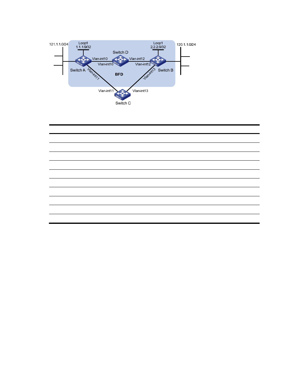
Figure 4 Network diagram
Table 5 Interface and IP address assignment
Device Interface
IP address
Switch A
VLAN-interface 10
12.1.1.1/24
Switch A
VLAN-interface 11
10.1.1.102/24
Switch A
Loopback 1
1.1.1.9/32
Switch B
VLAN-interface 12
11.1.1.1/24
Switch B
VLAN-interface 13
13.1.1.1/24
Switch B
Loopback 1
2.2.2.9/32
Switch C
VLAN-interface 11
10.1.1.100/24
Switch C
VLAN-interface 13
13.1.1.2/24
Switch D
VLAN-interface 10
12.1.1.2/24
Switch D
VLAN-interface 12
11.1.1.2/24
Configuration procedure
1.
Configure IP addresses for interfaces. (Details not shown.)
2.
Configure static routes and BFD:
# Configure static routes on Switch A and enable BFD control mode for the static route that
traverses Switch D.
<SwitchA> system-view
[SwitchA] bfd multi-hop min-transmit-interval 500
[SwitchA] bfd multi-hop min-receive-interval 500
[SwitchA] bfd multi-hop detect-multiplier 9
[SwitchA] ip route-static 120.1.1.0 24 2.2.2.9 bfd control-packet bfd-source 1.1.1.9
[SwitchA] ip route-static 120.1.1.0 24 vlan-interface 11 10.1.1.100 preference 65
[SwitchA] quit
# Configure static routes on Switch B and enable BFD control mode for the static route that
traverses Switch D.
<SwitchB> system-view
[SwitchB] bfd multi-hop min-transmit-interval 500
[SwitchB] bfd multi-hop min-receive-interval 500
[SwitchB] bfd multi-hop detect-multiplier 9