Configuring router connections, Ed them. see – Grass Valley Kaleido-X v.7.80 User Manual
Page 401
393
Kaleido-X
User’s Manual
cables plugged into the expansion ports on the router cards themselves, and then, in XEdit,
you must have specified how the cards are connected. Refer to “Configuring Router Card
Expansion” in the Kaleido-X (7RU) Hardware Description & Installation Manual, for details.
Configuring Router Connections
To configure router connections
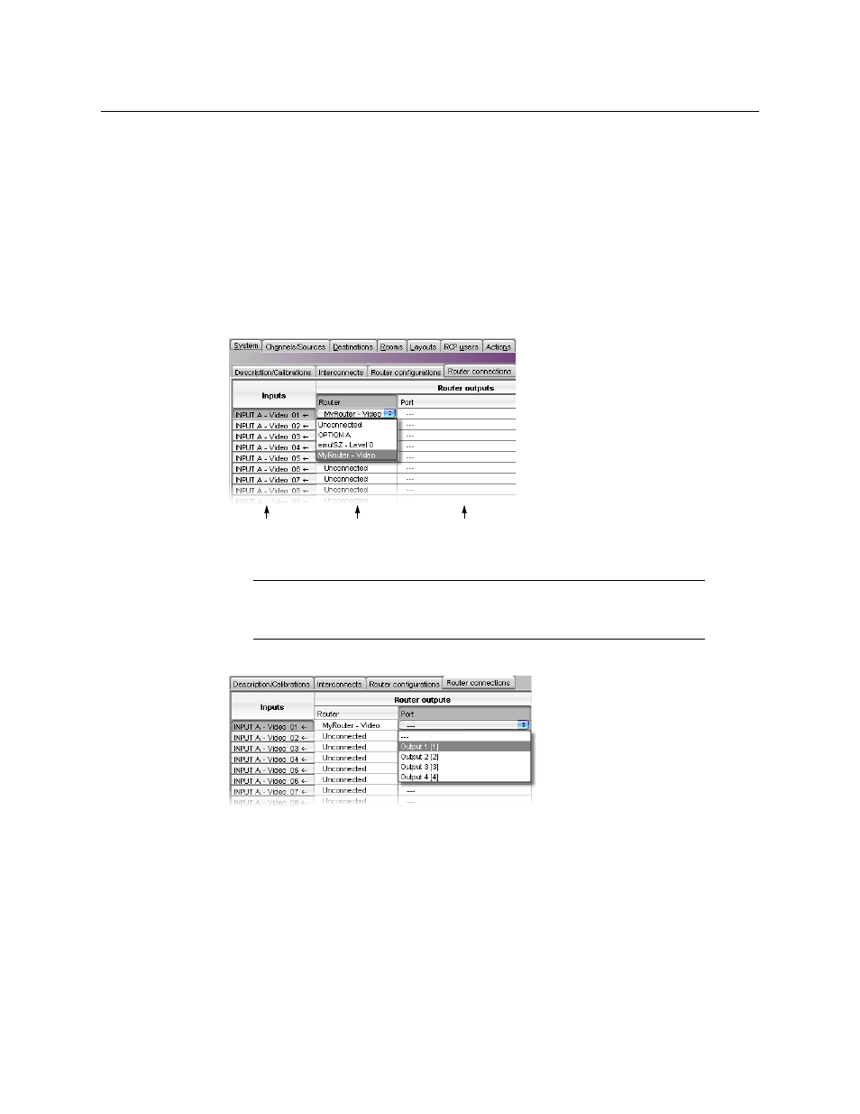
1 Click the Router connections tab, which lists all multiviewer inputs and, for each, the
associated output connector from a router. For each multiviewer input you wish to
connect to an external router (e.g., INPUT A – Video 01), click the first menu (under
Router) and choose a physical router level (e.g., “MyRouter” – Video).
2 Click the second menu and choose the appropriate output (e.g., “Output 1 [1]”).
In this example, the Kaleido-X software registers that Output 1 from the router has a
cable that connects to the BNC connector corresponding to Video 1 on the
multiviewer’s INPUT A module. This means that when you select a router source to be
assigned to a monitor on the monitor wall, the Kaleido-X software will be able to
determine whether the multiviewer’s INPUT A – Video 01 connector is available, and, if
so, request the appropriate crosspoint change for “Output 1” of “MyRouter”.
3 Use the incremental copy tool to assign the next router outputs to contiguous
multiviewer inputs.
Note:
Unconnected means that this multiviewer input is not connected to a
router output. For example, the input might be directly connected to a
source signal.
Maps to BNC
connectors on the
multiviewer
The name of
the physical
router
Maps to OUTPUT
BNC connectors on
the physical router