Grass Valley Kaleido-X v.7.80 User Manual
Page 423
Advertising
415
Kaleido-X
User’s Manual
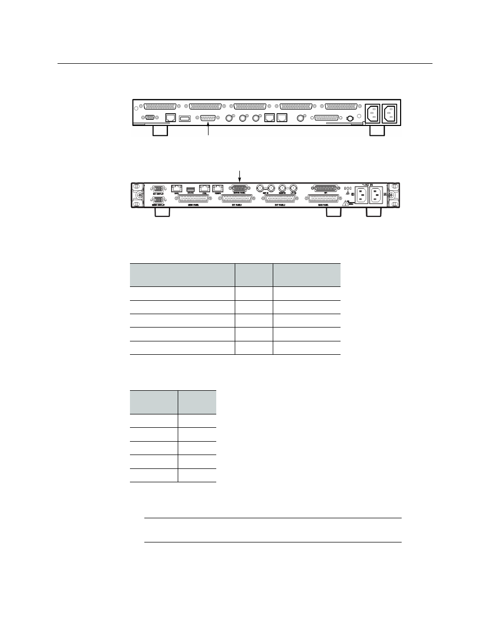
• On an SCU (MKS-8010A or MKS-8010B), use the 15-pin connector labeled EDITOR
PANEL, with an adapter.
Sony System Control Unit (MKS-8010A)
Sony System Control Unit (MKS-8010B)
To use a serial tally from an SCU model MKS-8010A or MKS-8010B, a 15-pin-to-9-pin
adapter is required, with pinouts as follows:
No adapter is required for SCU model MKS-8010, which has a DE-9 connector with the
following pinout:
In addition, on Sony menu page 7367, you must enable R and G serial tallies on the SCU
port.
MKS-8010A or MKS-8010B
(15-pin)
SCU
(Signal)
Serial tally device
(9-pin)
2
RX-
2
3
TX+
3
10
RX+
7
11
TX-
8
4
GND
4
MKS-8010
(9-pin)
SCU
(Signal)
2
RX-
3
TX+
7
RX+
8
TX-
4
GND
Note:
on page 26 for pinouts on the
multiviewer.
EDITOR PANEL
EDITOR PANEL
Advertising
This manual is related to the following products: