Magnum Energy ME-RTR Router User Manual
Page 51
Page 43
©
2014 Magnum Energy, Inc.
Setup
TECH: 02 Port Vers/RTR=3.1
Displays the version of all router-connected units and the port #s to which they are assigned (P1-6).
Info: The router version displays on the top line of the screen of the TECH’s versions
menu item.
Info: The BMK, AGS, and the remote accessories may display a “0.0” version for several
reasons. Either the accessory is not installed, there is no communication because of a
bad or miswired network cable, the device is not powered, or the device is bad.
TECH: 03 AccPort Versions
The AccPort Versions menu displays the version of all inverter-connected accessories and the
port #s to which they are assigned (P1A-6A).
TECH: 04 Fault History
This menu provides a two-screen display (only one screen display for AGS faults) of historic
information for each of the last 9 inverter and AGS fault records. Info for each fault displays from
the most recent fault (H1) to the previous/past faults (H2 up to H9). See Figure 3-19 for examples
of inverter fault history screens, and Figure 3-20 for an example of an AGS fault history screen.
Note: If no faults are on record, the display will show “ No Fault History”.
Info: All recorded fault history records will be retained (except for the “days since fault”
display), even if power is removed from the router.
• INV
Faults – Select to display a history of the last nine inverter faults.
• AGS
Faults – Select to display a history of the last nine AGS faults.
• Clear All Faults – Select to clear all recorded fault history. Per directions on screen, press
and hold the SELECT knob for ~ 5 seconds until the screen displays “All Fault History cleared”.
You are then returned to the 04 Fault History main menu.
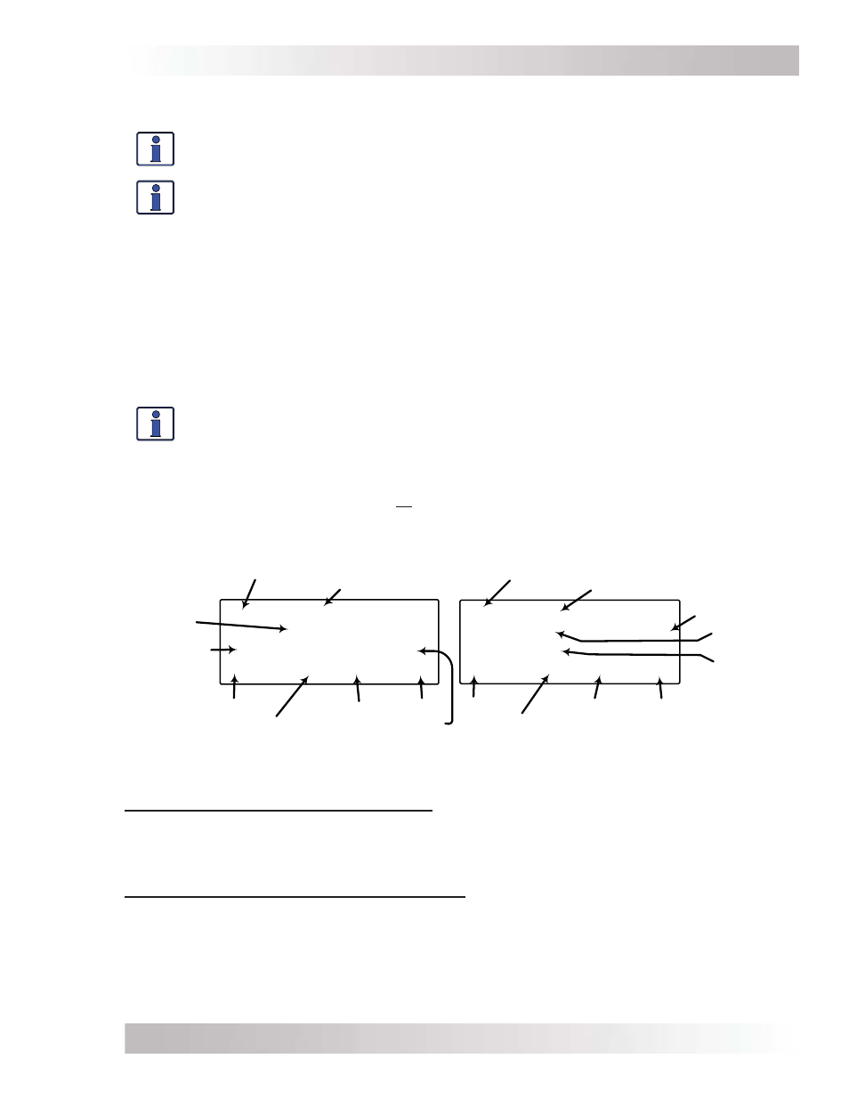
Port
H1A Low Battery
Off
21.0VDC 12.0ADC
P1 3 11:52A INV
Port
Days since fault
Time
Menu
Fault Mode
DC Battery
Voltage
Status
DC Amps
Fault History Number
H1B Low Battery
BTS 77F Tfmr 114F
FETs 102F
P1 3 11:52A INV
Days since fault
Time
Menu
Fault Mode
Transformer,
Battery,
and FET
Temps
Fault History Number
Figure 3-19, Inverter Fault History (fi rst and second screens)
Figure 3-19 – first screen (left graphic): The top line displays the fault history number, first
screen (A), and the recorded fault mode. The second line displays the status of the inverter/charger
at the time of the fault. The third line displays DC battery voltage and amperage readings at the
time of the fault. The bottom line displays the port that the fault occurred at, how many days ago
the fault occurred, the time of the fault, and the menu in which it occurred.
Figure 3-19 – second screen (right graphic): The top line displays the fault history number,
second screen (B), and the recorded fault mode. The second and third line display transformer,
battery, and FETs temperatures at the time of the fault. The bottom line displays the port that
the fault occurred at, how many days ago the fault occurred, the time of the fault, and the menu
in which it occurred.