3 on/off buttons, 4 menu buttons, 5 rotary select knob – Magnum Energy ME-RTR Router User Manual
Page 62: 6 aux relay led indicator
©
2014 Magnum Energy, Inc.
Page 54
Operation
5.1.3 ON/OFF
Buttons
• ON/OFF
INVERTER: This button toggles the inverter function on and off. The green INV LED
turns on and off with the button.
• ON/OFF
CHARGER: This button toggles the charger function on and off after it is actively
charging. This button is also used to initiate an Equalize charge. For more information on
using the Equalize charge feature, see Section 5.2.2 and the Equalizing mode information on
pages 59-60.
5.1.4
Menu Buttons
These five buttons provide quick access to menu items for configuring, monitoring, and
troubleshooting your inverter/charger system.
• PORT: This button scrolls through the active communication ports (P1-P6). Pressing the PORT
button will skip over non-active or empty ports allowing quick access to connected devices.
• CTRL: This button contains the AC In Control, Charger Control, Gen Control, and RTR Aux Relay
menus. The CTRL button gives you quick control of the main functions of the inverter/charger.
• METER: This button provides meter information on the inverter/charger, and the ME-AGS-N
and ME-BMK/ME-BMK-NS (if connected). See Section 3.3.3 for more detailed information.
Info: If the LCD display becomes unreadable, press and hold the METER button until
the System Home screen shows (~3 seconds) to refresh the LCD display.
• SETUP: This button allows the router, the inverter/charger, and any connected accessory to be
confi gured to your specifi c system preferences. See Section 3.3.4 for more detailed information.
• TECH: This button allows you to access menu selections that can help service personnel with
troubleshooting, and also allows the factory default settings for the inverter/charger and any
connected accessory to be restored. See Section 3.3.5 for more detailed information.
5.1.5
Rotary SELECT Knob
The rotary SELECT knob is used to view and select various menu items and settings displayed on
the LCD screen. Turn clockwise/counterclockwise to view the different menu items and available
settings. Press the SELECT knob to select/enter a menu item or to save a setting once it is displayed
on the LCD screen.
Info: All adjustable settings in the router (except for SETUP: 01B Screen Setup, CTRL:
03 Gen Control and TECH: 07 Show all Menus—which revert back to default) are saved
in non-volatile memory and are preserved until changed—even if an inverter reset is
performed or if all power to the router or inverter is removed.
CAUTION: An accessory that is networked to the inverter may have adjustable settings
that revert back to default if all power to the inverter is lost. Refer to the owner’s
manual for the particular accessory to determine if any setting is affected.
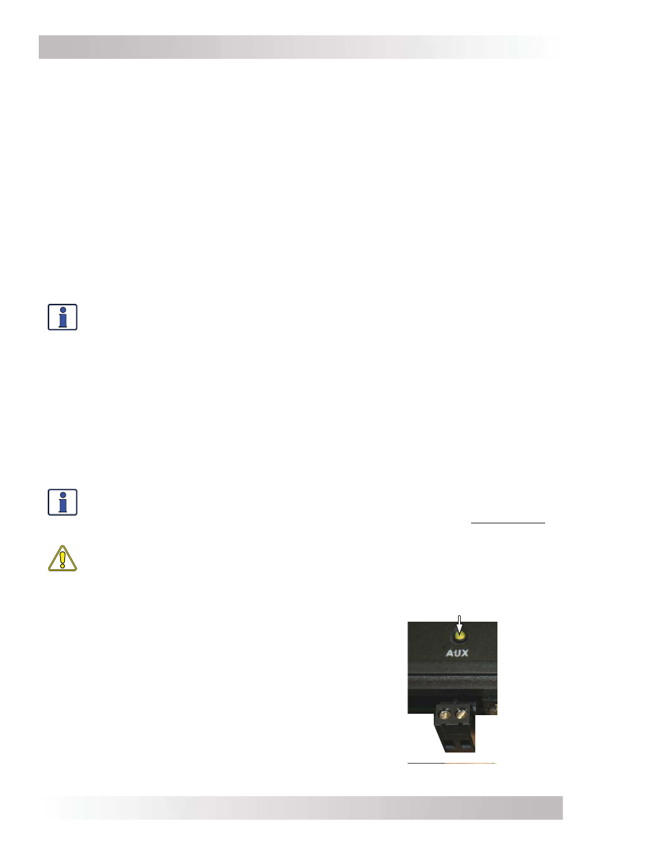
Aux Relay LED Indicator
Figure 5-2, Aux Relay LED
5.1.6
Aux Relay LED Indicator
The yellow Aux LED indicator allows a visual indication of the
Aux Relay operation. The LED will be ON when the relay is
closed (energized), and will be OFF when the relay is open
(de-energized). See Figure 5-2.
What is the Aux Relay used for? The most common use
is to turn on an exhaust fan to eliminate your battery bank
gasses using the VDC start and stop settings. The Aux Relay
can also be used to control the coil of a current carrying relay.
How do I adjust the Aux Relay? The SETUP: 01F RTR
Aux Relay menu is used to determine the conditions (DC
volts, inverter fault, or battery SOC) at which the relay
automatically opens and closes.