Magnum Energy ME-RTR Router User Manual
Page 66
©
2014 Magnum Energy, Inc.
Page 58
Operation
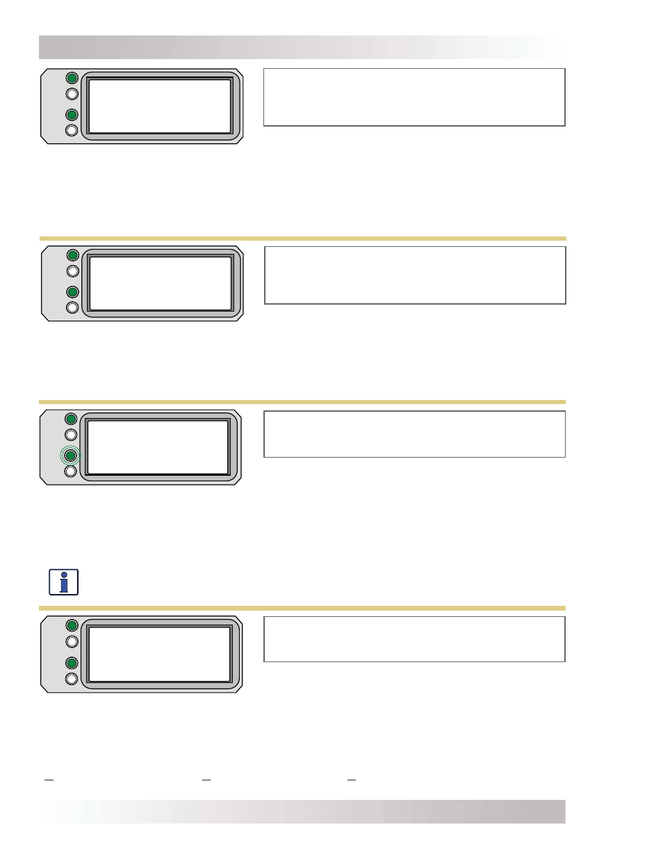
FAULT
PWR
CHG
INV
Absorb Charging
Settings/Info...
Absorb Charging appears on LCD. PWR (green) LED is on
solid. CHG (green) LED is typically on solid, but may blink.
FAULT (red) LED is off, and INV (green) LED could be on or off.
Figure 5-10, Absorb Charging Mode
• Absorb Charging (Absorb) – The Absorb Charge state is the constant voltage stage and
begins when the absorb voltage is reached (determined by the SETUP button’s 03C Battery Type
setting) while Bulk charging. During this stage, the DC charging current decreases in order to
maintain the absorb voltage setting. This charge stage continues until the 03D Absorb Done (Time,
Amps, or SOC) or 03E Max Charge: Time setting is reached.
Charger Standby appears on LCD. PWR (green) LED
is on solid and CHG (green) LED blinks. FAULT (red)
LED is off, and INV (green) LED could be on or off.
FAULT
PWR
CHG
INV
Bulk Charging
Settings/Info...
Bulk Charging appears on LCD. PWR (green) LED is
on solid. CHG (green) LED is typically on solid, but may
blink. FAULT (red) LED is off. INV (green) LED could be
on or off.
• Bulk Charging (Bulk) – The battery charger is delivering maximum current (determined by
the SETUP button’s 03E Max Charge: Rate setting) to the batteries. The charger will remain in
Bulk charge until the absorb voltage (determined by the SETUP button’s 03C Battery Type menu
setting) or the 03E Max Charge: Time setting is reached.
Figure 5-11, Bulk Charging Mode
FAULT
PWR
CHG
INV
Charger Standby
Settings/Info...
Figure 5-12, Charger Standby Mode
Charging appears on LCD. PWR (green) and CHG
(green) LEDs are on solid. FAULT (red) LED is off, and
INV (green) LED could be on or off.
FAULT
PWR
CHG
INV
Charging
Settings/Info...
• Charging
(Charge) – Once Charge mode has been enabled, the unit will wait and display
“Charging” to determine the charge routine. The charger will initiate Bulk Charging if connected
to AC based on SOC, the battery type is CC/CV, or if the DC voltage is low (≤12.8 VDC / 12-volt
models, ≤25.6 VDC / 24-volt models, or ≤51.2 VDC / 48-volt models). If the DC voltage is high
(≥12.9 VDC / 12-volt models, ≥25.6 / 24-volt models, or ≥51.2 / 48-volt models), the charger will
skip the Bulk and Absorb charging stages and go directly to the fi nal charge stage (Float or Silent).
Figure 5-13, Charging Mode
• Charger Standby (Chg Stby) – This indicates the charger has been disabled to prevent
further charging, but the AC power (from utility or generator) to the AC input is still available on
the AC output. This display is shown when the ON/OFF CHARGER button is pressed while the AC
power is passing through the inverter/charger.
Info: Press the ON/OFF CHARGER button to enable charging again. When enabled, the
charger continues in the previous charge mode and the CHG (green) LED comes on solid.