Magnum Energy ME-RTR Router User Manual
Page 69
Page 61
©
2014 Magnum Energy, Inc.
Operation
• Load Support AAC (LS-AAC) – This display indicates the Load Support (Amps AC) feature
is active because the inverter loads are requiring more power than the incoming AC source can
provide on its own. The inverter pulls the additional current needed for the loads from the inverter
batteries to keep the incoming AC current from exceeding the SETUP: 03A AC Input Amps setting.
Info: The Load Support AAC feature operates in parallel with the AC input to support the
inverter loads and is only available on MSH Series inverter/chargers. It is only active when
the AC input is connected and the inverter is enabled (INV LED is on).
Info: When the inverter is in Charge mode, the battery current (under the METER/01B
Inv/Chg DC Amps menu) is normally a positive value to show charging. However, in
Load Support AAC mode, the battery current reading is a negative number to indicate
how much current is being removed from the inverter batteries. The inverter batteries
will continue to provide current to assist the AC input current until the battery reaches
0.5 volts (12-volt systems), 1.0 volts (24-volt systems), and 2.0 volts (48-volt systems)
above the SETUP: 02B LBCO Volts setting.
FAULT
PWR
CHG
INV
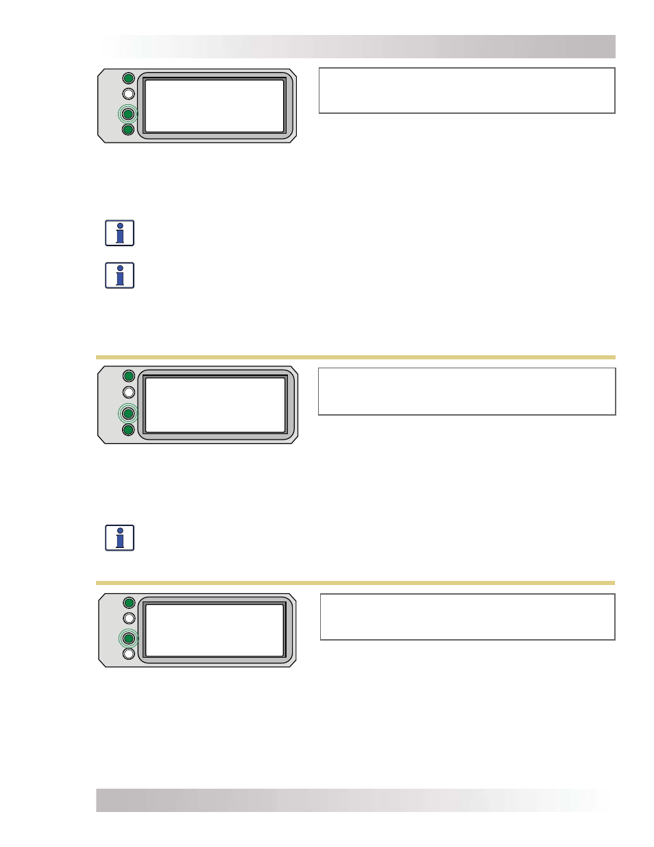
Load Support AAC
Settings/Info...
Load Support AAC appears on LCD. PWR (green) LED
is on solid and CHG (green) LED blinks. FAULT (red)
LED is off, and INV (green) LED is on solid.
Figure 5-19, Load Support AAC Mode
Load Support VDC appears on LCD. PWR (green) LED
is on solid and CHG (green) LED blinks. Fault (red) LED
is off, and INV (green) LED is on solid.
FAULT
PWR
CHG
INV
Load Support VDC
Settings/Info...
Figure 5-20, Load Support VDC Mode
• Load Support VDC (LS-VDC) – This display indicates the Load Support (Volts DC) feature is
active because an external DC source (solar, wind, etc.,) is providing more current than needed—
causing the battery voltage to rise. The inverter/charger reduces the incoming AC current to keep the
battery voltage from rising above the temperature-compensated SETUP: 03C Battery Type setting.
Info: The Load Support VDC feature operates in parallel with the AC input to support the
inverter loads and is only available on MSH Series inverter/chargers. This feature is only
active in Absorb, Float, EQ or Constant Voltage charge modes and when the inverter is
enabled (INV LED is on); it is deactivated if the charger is in Charger Standby.
FAULT
PWR
CHG
INV
Silent
Settings/Info...
Silent appears on LCD. PWR (green) LED is on solid
and CHG (green) LED blinks. FAULT (red) LED is off,
and INV (green) LED could be on or off.
Figure 5-21, Silent Mode
• Silent – This displays at the end of the Absorb charge stage if Silent is selected from the SETUP:
03F Final Charge Stage menu, or at the end of the Constant Voltage stage [if CV Chg Done Time (or
Amps) is selected under the SETUP: 03C Battery Type: CC/CV menu]. In Silent mode, the charger
is not actively charging but does monitor the battery voltage. If the voltage reaches the Set DC
Volts to ReBulk setting (under the 03F Final Charge Stage menu), or the Set DC Volts to Recharge
setting (under the 03C Battery Type: CC/CV menu), the charger will restart another charge cycle and
then transition back into Silent mode at the end of the Absorb (or Constant Voltage) charge cycle.