Rugged Cams Workhorse DVR 4 Channel User Manual
Page 13
12
Connecting the external sensors
Connect the external sensor cables to S1 ~ S4 on the input ports of the DIO (sensor/relay)
extension module with the GND symbol.
Each input port may be used regardless of the channel number.
Example - Connecting three external sensors
Connect the external sensor cable to the sensor input ports as shown below:
External Sensor
Input Port
Ground Port
Sensor 1
S1
GND
Sensor 2
S3
GND
Sensor 3
S4
GND
Sensor types include Normal Close (NC) or Normal Open (NO). For more information on
sensor type setting, see
{5-1-2 Recording Setup} {(7) Event Setup} {(B) Sensor}.
Normal Close (NC): Opens in case of incoming signal when closed normally
Normal Open (NO): Closes in case of incoming signal when opened normally
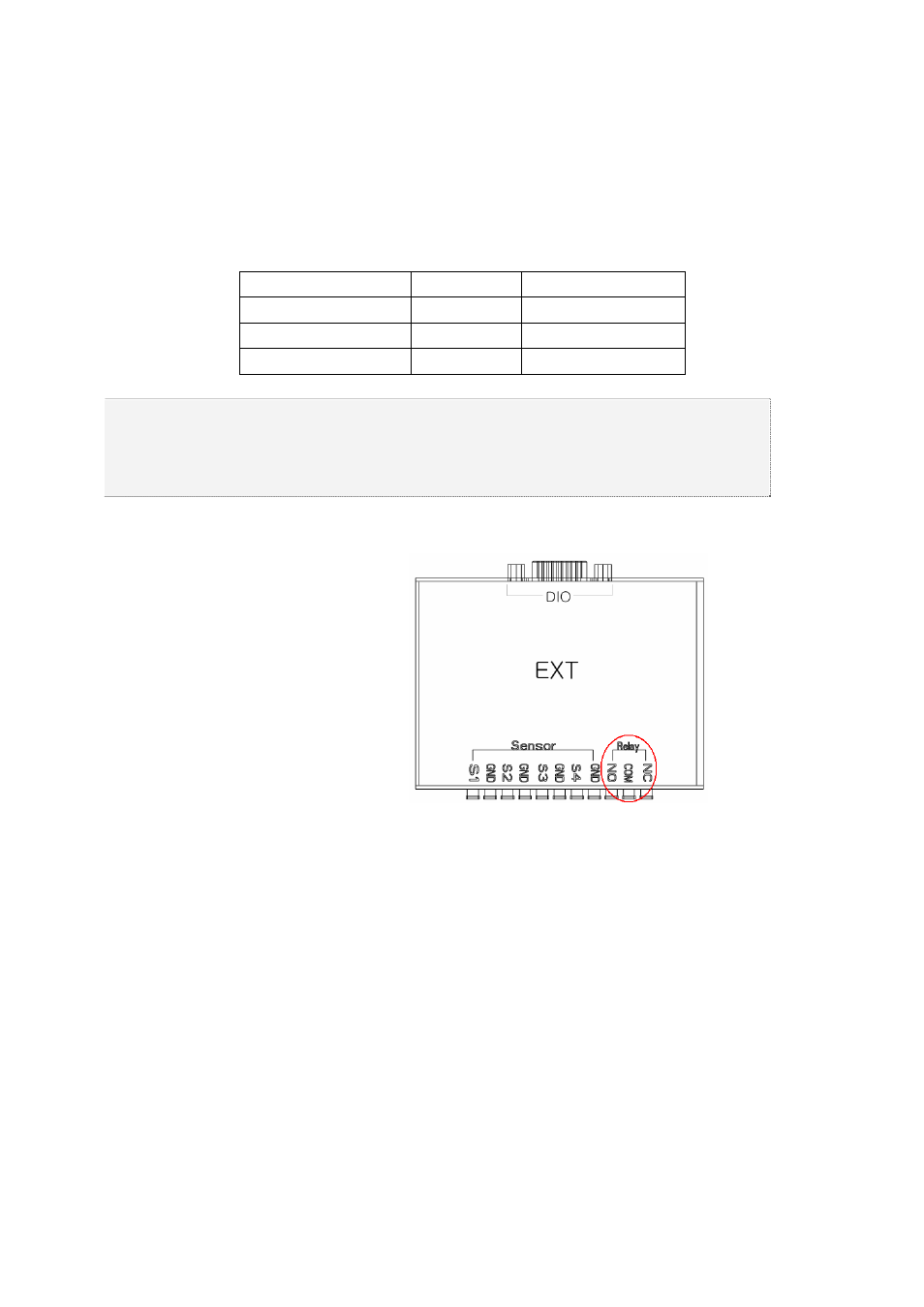
B) Relay connection
Relay output port
Connect the alarm light or external alarm device to the relay output port to generate alarms
through the external alarm device.
Connect the external alarm device to the COM or NC/NO output port of the DIO (sensor/relay)
extension module.
Example - Connecting one external sensor
Connect the external sensor cable to the relay output port:
External Alarm Device
Output Port
Ground Port
Relay 1
NC or NO
COM
Relay types include Normal Close (NC) or Normal Open (NO). For more information on
relay setting, see
{5-1-2 Recording Setup} {(8) Alarm Output} {(C) Relay}.
Normal Close (NC): Opens in case of incoming signal when closed normally
Normal Open (NO): Closes in case of incoming signal when opened normally