Usb converter – CIRCUTOR CVMk2 Series User Manual
Page 126
Advertising
126
CVM
k2
OPERA
TION
126
CVM
k2
COMMUNICA
TION
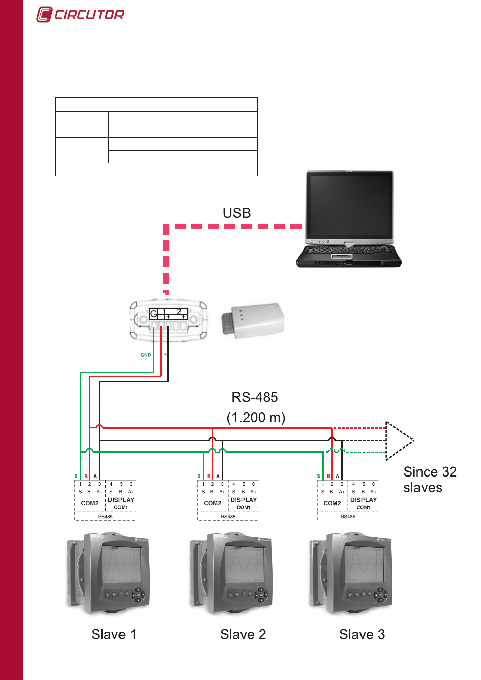
8.2.3. USB CONVERTER
The connection between the PC and the measurement module using a USB to RS-485
converter is showed in the figure below.
CONNECTOR
DESCRIPTION
1
+
RS-485 -
-
RS-485 +
2
+
RS-485 -
-
RS-485 +
G
Ground
The USB converter output pins are described
in the following table.
Advertising
See also other documents in the category CIRCUTOR Measuring instruments:
- QNA500 series (111 pages)
- Wi-beee Series (32 pages)
- CVM-C5 Series (40 pages)
- CVM-C10 Series (82 pages)
- CVM-MINI Series (26 pages)
- CVM-NET Series (2 pages)
- CVM-NET4 (7 pages)
- CVM-1D Series (2 pages)
- CVM-BDM Series (32 pages)
- PowerNet Series (2 pages)
- CVM-NRG96 Series (Available until stocks) (38 pages)
- CVM-B Series (320 pages)
- CVM96 Series (44 pages)
- CVM144 Series (58 pages)
- RS2RS (2 pages)
- TCP1RS+ (2 pages)
- EDS Series (5 pages)
- CMBUS series (24 pages)
- EDS-3G Series (6 pages)
- MDC-4 (30 pages)
- LM50-TCP+ (2 pages)
- MDC-20 (58 pages)
- ReadWatt Series (22 pages)
- CIRLAMP Series (102 pages)
- PowerStudio Series (42 pages)
- PowerStudio Series (110 pages)
- PowerStudio Series (110 pages)
- PowerStudio Series (292 pages)
- OPC Server PS/PSS (22 pages)
- SQL Data Export (28 pages)
- AR6 Series (69 pages)
- AR5L Series (52 pages)
- CIRe3 Series (50 pages)
- CIReQ (36 pages)
- QNA-P Series (36 pages)
- T3V Series (8 pages)
- CPM (Available until stocks) (20 pages)
- DHB Series (58 pages)
- DHB Series (46 pages)
- DHB Series (54 pages)
- DHB Series (50 pages)
- EMF-EMB Series (11 pages)
- SYNCHROMAX Series (2 pages)
- SYNCHROMAX Series (2 pages)