Analogue outputs configuration – CIRCUTOR CVMk2 Series User Manual
Page 55
55
CVM
k2
CONFIGURA
TION
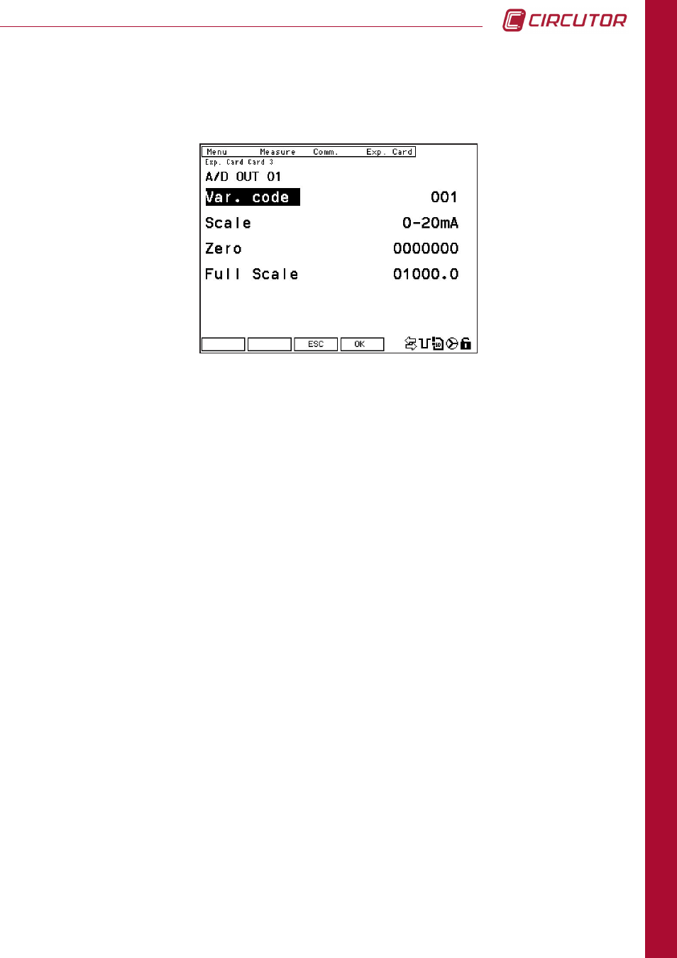
4.7.3.1. Analogue outputs configuration
The card's analogue outputs configuration screen is shown in the following screen:
The analogue outputs' configuration parameters are:
Var. code
: Real time electric variable code to be assigned to the output (see Chapter 8.3,
Modbus Memory Map, to see the codes for all variables).
Energy code not permitted.
Scale
:
It is possible to select between
0
and
4
, which correspond to scales 0...20 mA
and 4...20 mA, respectively.
Zero
:
The variable should be assigned this value to have an output of 0 or 4 mA
(depends on the scale selected).
Bottom of scale
.: The variable should be assigned this value to have an output of 20 mA.
The function buttons give us the following options when in edit mode:
ESC
: Exit the current menu without saving changes.
OK
: Confirm and save the changes made.
The different buttons that appear on this screen are:
Next
: This button is clicked to increase the output number up to a maximum of 4 (
A/D OUT
04
). Click it again to return to output 01 (
A/D OUT 01
).
IN
: From any screen, click on this button to go to the analogue inputs' configuration
screen. (Section 4.7.3.3. Analogue Inputs Configuration)
EDIT
: Click on this option to access the edit menu. The arrow buttons are used to select the
parameter to be modified (in bold). Enter by pressing the
SET
Button.