CIRCUTOR CVMk2 Series User Manual
Page 17
17
CVM
k2
INST
ALLA
TION
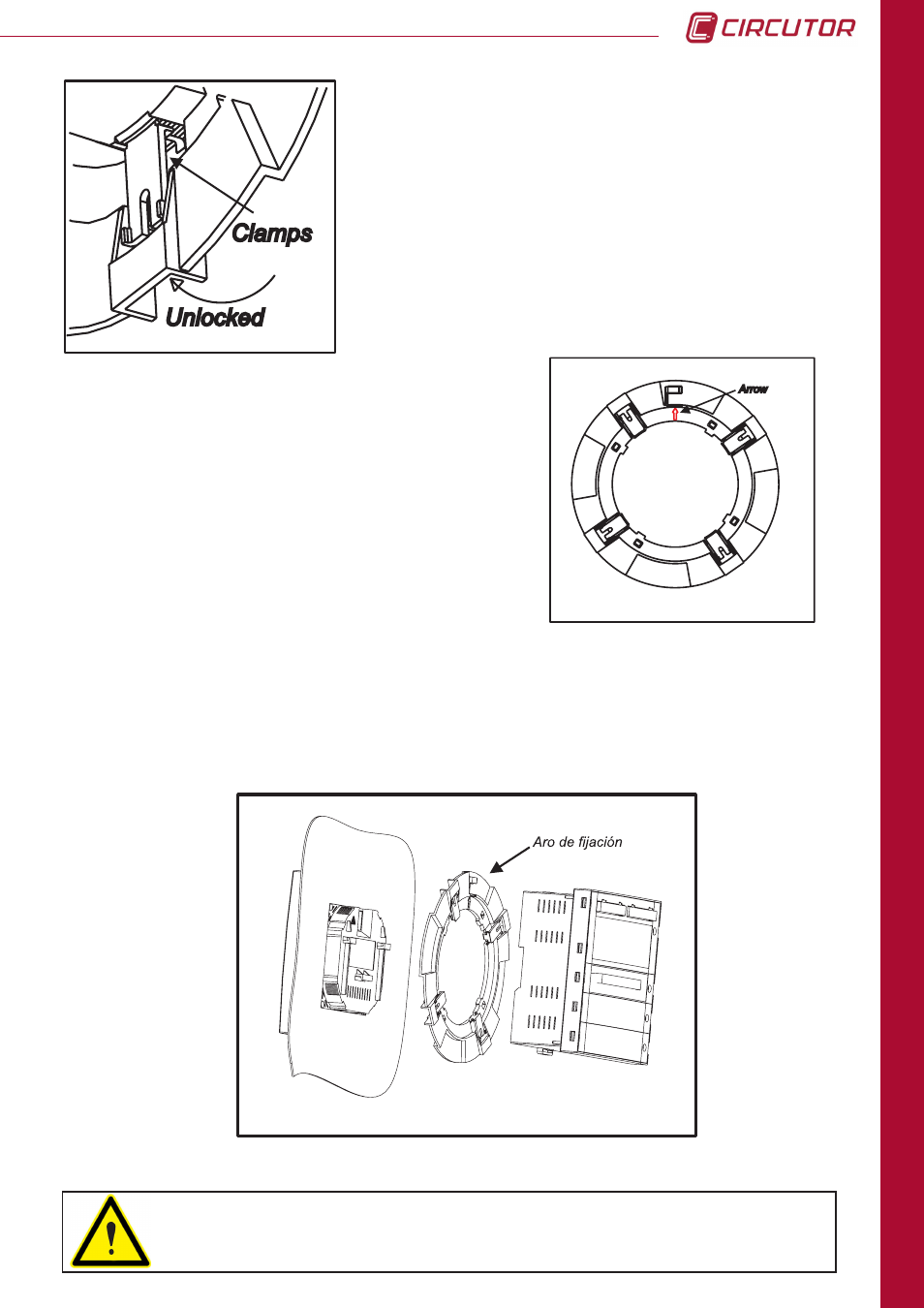
As shown in the figure, the guide arrow should point
upward and line up with the arrow found on the rear of
the viewer or display screen. The arrow points to the
position where the RJ-45 communications cable and
the display screen power supply cables run out.
A zoomed view of the previous image is provided in the
figure. It provides a detailed view of the movements
necessary to lock and unlock
CVMk2 display screen
mount ring.
The mount diagram is shown in the following figure. The measuring unit can then be mounted
on the ring behind the display screen, or it can be installed on a DIN rail and communicate
with the display screen via a communication cable and transparent RJ-45 power supply. (See
Table 3.1, physical description).
To install the screen in a panel as shows the 2.3 installations methods, you
have to use a flat surface of a type 1 enclosure.