CIRCUTOR CVMk2 Series User Manual
Page 33
33
CVM
k2
CONFIGURA
TION
The cursor will be positioned over the first digit, corresponding to the largest value. Use the
left/right arrow buttons to navigate from one digit to another and the up/down arrow buttons to
increase/decrease the value of the digit where the cursor is currently positioned.
To save the modified parameters to memory, press
OK
(F4) before exiting. If saving the changes
is not desired, press
ESC
(F3).
Parameters that can be configured on this screen are:
•
SWELL T
hr
: This corresponds to the threshold value, in %, to detect an overvoltage event.
•
SAG T
hr
: This corresponds to the threshold value, in %, to detect a hole event.
•
iNTEr. T
hr
: This corresponds to the threshold value, in %, to detect a short circuit event.
•
SWELL H
ys
: Hysteresis, in %, over the programmed value in the detection threshold.
•
SAG H
ys
: Hysteresis, in %, over the programmed value in the detection threshold.
•
iNTER. H
ys
: Hysteresis, in %, over the programmed value in the detection threshold.
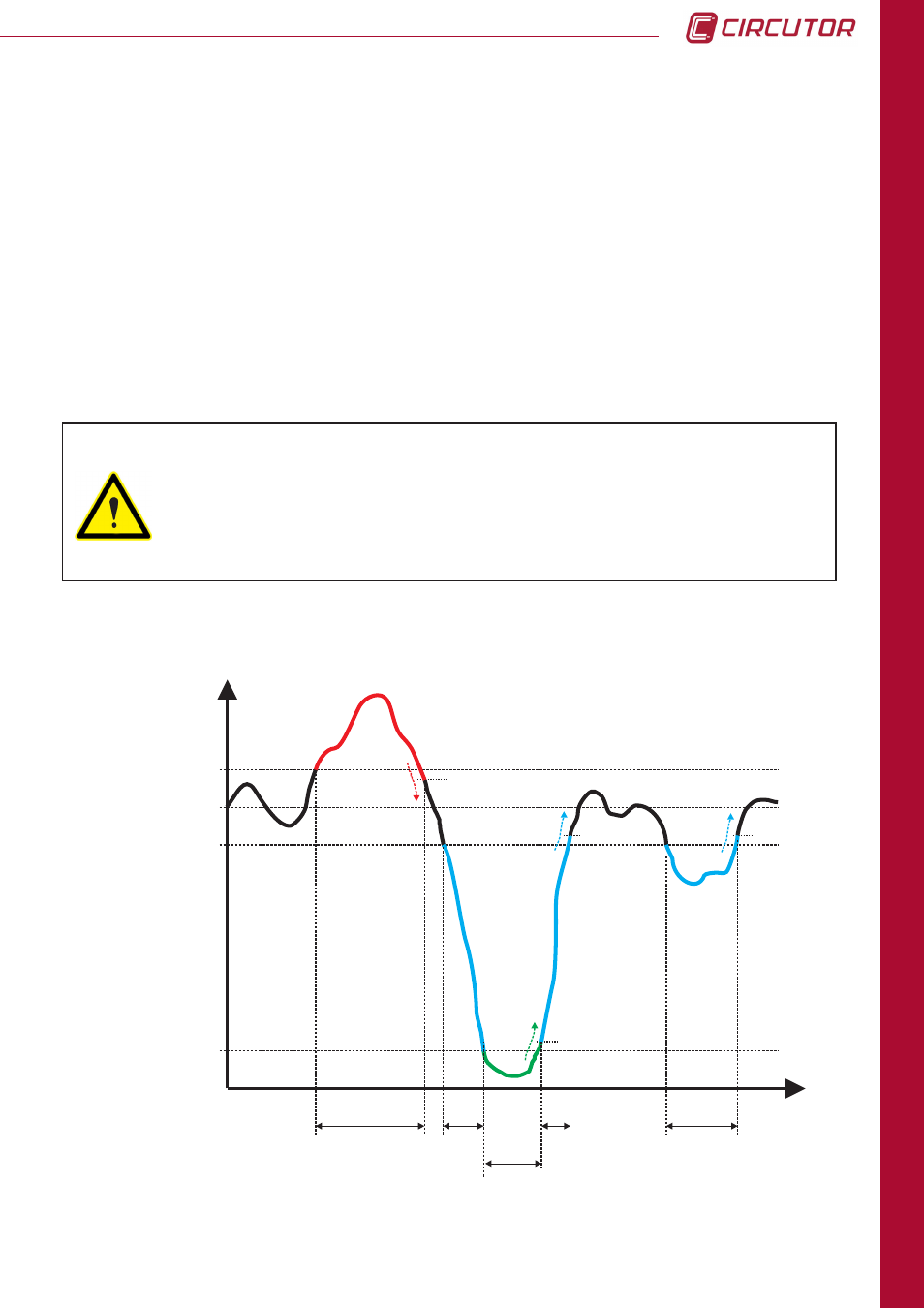
Inter Thr.
U
n
t
Sag Thr.
Swell Thr.
V nom
Swell Hys
Inter Hys
t 0
t 2
t 4
t 1
t 3
10%
90%
110%
Sag Hys
Sag Hys
In the graph is showed an example of an Swell voltage in the interval t 0. The time of that
overvoltage event is the time that the signal is over the swell value (usually 110%) plus the time
of the hysteresis for this swell (usually 2%).
Example graph:
The value of the hysteresis is always, in part, more restrictive. It is not a
symmetric hysteresis. The detection value is over the programmed value, as a
%. The hysteresis applies in the disconnection or the disappearance of the event.
If the event is for a maximum (
over v T
hd
), the hysteresis will be applied when
the signal drops. If the event is for a minimum (
hole T
hd
and
short circuit T
hd
),
the hysteresis will be applied when the signal increases again.