5 terminals description, 1 tag for voltage and ct connections, 2 power supply and communications tag – CIRCUTOR CVMk2 Series User Manual
Page 20
20
CVM
k2
INST
ALLA
TION
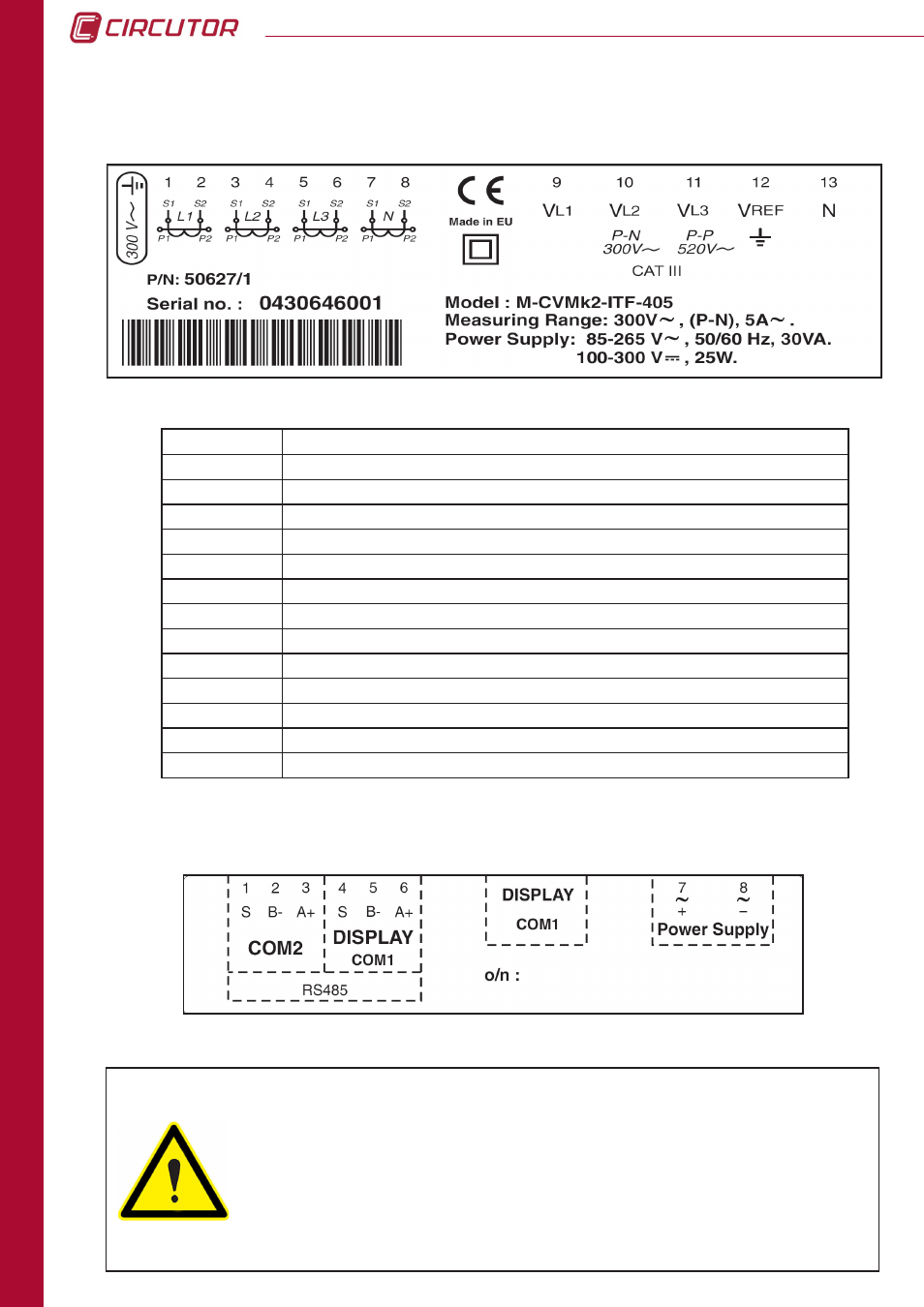
TERMINAL
DESCRIPTION
1
Current transformer, L1 phase S1 connection
2
Current transformer, L1 phase S2 connection
3
Current transformer, L2 phase S1 connection
4
Current transformer, L2 phase S2 connection
5
Current transformer, L3 phase S1 connection
6
Current transformer, L3 phase S2 connection
7
Current transformer, neutral line S1 connection
8
Current transformer, neutral line S2 connection
9
L1 phase voltage input
10
L2 phase voltage input
11
L3 phase voltage input
12
Input voltage V
REF
(GND)
13
Input voltage NEUTRAL LINE
2.5.1 TAG FOR VOLTAGE AND CT CONNECTIONS
Product to be protected by an external fuse, model KTK-1 by
Bussmann, or similar, rated 600V, 1A. It should be provided with a
MCCB or equivalent device to switch off the system from the power
supply circuit. The power supply and voltage measuring circuit is
connected with cable minimum cross section of 1 mm
2
(AWG 17). The
current transformer secondary side connection line should have a
minimum cross section of 2 mm
2
(AWG 14 Cu) and with a minimum
temperature rating of 60 ºC.
2.5.2 POWER SUPPLY AND COMMUNICATIONS TAG
2.5 TERMINALS DESCRIPTION