Digital outputs configuration – CIRCUTOR CVMk2 Series User Manual
Page 43
43
CVM
k2
CONFIGURA
TION
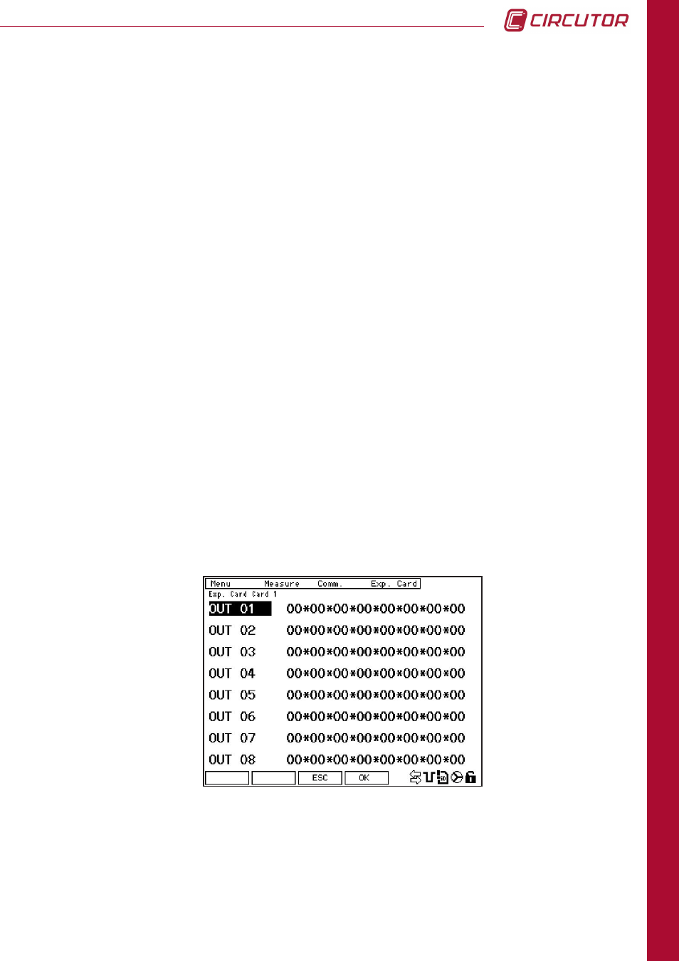
4.7.1.2. Digital outputs configuration
On this screen, equations are configured for the alarms that are applied to activate the system
outputs. Equations can be configured using AND (*) and/or OR (+) functions between one or
more of the 16 previously configured alarms (see Section 4.7.1.1., Alarm Configuration), in
order to activate each one of the card's 8 digital outputs.
To modify the card equations' configuration parameters, press the
EDIT
button (F4). Select the
output to be configured and press
SET
to begin editing.
4.7.1.1.b Reverse configuration logic output
When a variable code corresponding to the status of an expansion card input is selected, an
alarm can be activated in one of two possible ways: direct or inverse logic.
To configure the alarms using direct logic, with respect to the input, [i.e., the alarm activates
(value = 1) when the input activates (value = 1)], the parameters should be configured as
follows:
max
= 1 and
min
= -1.
To configure the alarms using inverse logic, with respect to the input, [i.e., the alarm activates
(value = 0) when the input deactivates (value = 1)], the parameters should be configured as
follows:
max
= 0 and
min
= 0.
Edit the two digits in the equation that correspond to the appropriate alarm. Between the two
digits corresponding to the alarm, an "*" or "+" sign can be entered. These correspond to the
AND or OR functions, respectively, and will be applied between the alarms configured.
Press
(F3) to return to the
ALARM 01
screen (Section 4.7.1.1).
Press
(F1) to return to the
inputs
screen (Section 4.7.1.3).