Interrupt request register initialization – Zilog Z86193 User Manual
Page 109
Z8
®
CPU
User Manual
UM001604-0108
Interrupts
102
The RAM Protect option is selected at ROM mask submission time or at EPROM program
time. If not selected or not an available option, this bit is reserved and must be 0.
Interrupt Request Register Initialization
The Interrupt Request Register (IRQ), displayed in
register that stores the interrupt requests for both vectored and polled interrupts. When an
interrupt is made on any of the six, the corresponding bit position in the register is set to 1.
Bit 0 to bit 5 are assigned to interrupt requests IRQ0 to IRQ5, respectively.
Whenever Power-On Reset (POR) is executed, the IRQ resister is reset to
00h
and dis-
abled. Before the IRQ register accepts requests, it must be enabled by executing an
ENABLE INTERRUPTS (EI) instruction.
Setting the Global Interrupt Enable bit in the Interrupt Mask Register (IMR, bit 7) does not
enable the IRQ. Execution of the EI instruction is required (see
For polled processing, IRQ must still be initialized by an EI instruction. To properly ini-
tialize the IRQ register, the following code is provided.
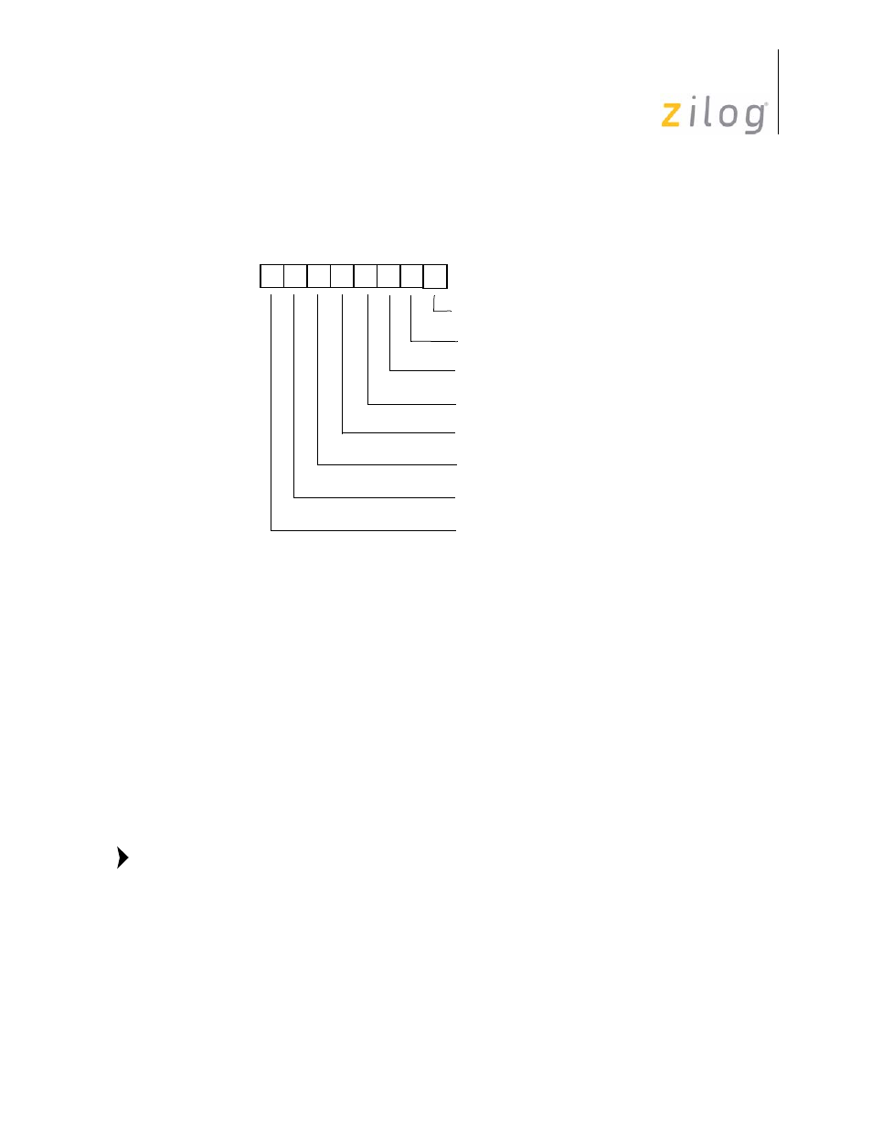
Figure 97. Interrupt Mask Register
CLR
IMR
// Make sure vectored interrupts are disabled.
D7 D6 D5 D4 D3 D2 D1 D0
(Read/Write)
Interrupt Request Register (IMR)
Register FBh
0 = Disables IRQ0
1 = Enables IRQ0
0 = Disables IRQ1
1 = Enables IRQ1
0 = Disables IRQ2
1 = Enables IRQ2
0 = Disables IRQ3
1 = Enables IRQ3
0 = Disables IRQ4
1 = Enables IRQ4
0 = Disables IRQ5
1 = Enables IRQ5
0 = Disables RAM Protect
1 = Enables RAM Protect
0 = Disables Interrupt
1 = Enables Interrupt
Note:
- Z86233 Z86243 Z86733 Z86743 Z86C02 Z86C04 Z86C08 Z86C15 Z86C21 Z86C30 Z86C31 Z86C33 Z86C36 Z86C40 Z86C43 Z86C61 Z86C62 Z86C63 Z86C65 Z86C83 Z86C90 Z86C91 Z86C93 Z86C96 Z86E02 Z86E03 Z86E04 Z86E06 Z86E07 Z86E08 Z86E15 Z86E21 Z86E30 Z86E31 Z86E33 Z86E34 Z86E40 Z86E43 Z86E44 Z86E61 Z86E63 Z86E83 Z86K15 Z86L02 Z86L04 Z86L08 Z86L16 Z8E000 Z8E001 Z8PE003