Zilog Z86193 User Manual
Page 124
Z8
®
CPU
User Manual
UM001604-0108
Serial Input/Output
117
To configure Z8
®
CPU for a specific bit rate, appropriate values as determined by the
above equation must be loaded into registers PRE0
(
F5h
) and T0 (
F4h
). PRE0 also controls the counting mode for T0 and should therefore be
set to CONTINUOUS mode (D0 = 1).
For example, given an input clock frequency (XTAL) of 11.9808 MHz and a selected bit
rate of 1200 bits per second, the equation is satisfied by p = 39 and t = 2. Counter/Timer
T0 should be set to
02h
. With T0 in Continuous Mode, the value of PRE0 becomes
9Dh
).
lists several commonly used bit rates and the values of XTAL, p, and t required to
derive them. This list is presented for convenience and is not intended to be exhaustive.
Table 24. Bit Rates
Bit Rate
7,3728
7,9872
9,8304
11,0592
11,6736
11,9808
12,2880
p
t
p
t
p
t
p
t
p
t
p
t
p
t
19200
3
1
–
–
4
1
–
–
–
–
–
–
5
1
9600
3
2
–
–
4
2
9
1
–
–
–
–
5
2
4800
3
4
13
1
4
4
9
2
19
1
–
–
5
4
2400
3
8
13
2
4
8
9
4
19
2
39
1
5
8
1200
3
16
13
4
4
16
9
8
19
4
39
2
5
16
600
3
32
13
8
4
32
9
16
19
8
39
4
5
32
300
3
64
13
16
4
64
9
32
19
16
39
8
5
64
150
3
128 13
32
4
128
9
64
19
32
39
16
5
128
110
3
175
3
189
4
175
5
157
4
207 17
50
8
109
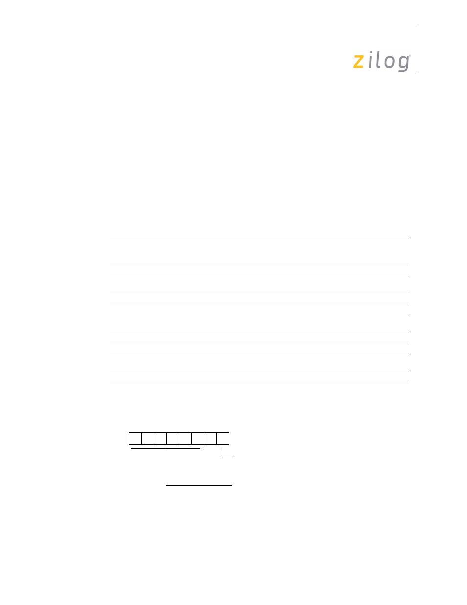
Figure 108. Prescaler 0 Register Bit-Rate Generation
D7 D6 D5 D4 D3 D2 D1 D0
(Write-Only)
Prescalar 0 Register (PRE0)
Register F5h
Count Mode
0 = T
0
Single Pass
(Range: 1-64 decimal, 01h–00h)
(Range: 1-64)
1 = T
0
Modulo-n
- Z86233 Z86243 Z86733 Z86743 Z86C02 Z86C04 Z86C08 Z86C15 Z86C21 Z86C30 Z86C31 Z86C33 Z86C36 Z86C40 Z86C43 Z86C61 Z86C62 Z86C63 Z86C65 Z86C83 Z86C90 Z86C91 Z86C93 Z86C96 Z86E02 Z86E03 Z86E04 Z86E06 Z86E07 Z86E08 Z86E15 Z86E21 Z86E30 Z86E31 Z86E33 Z86E34 Z86E40 Z86E43 Z86E44 Z86E61 Z86E63 Z86E83 Z86K15 Z86L02 Z86L04 Z86L08 Z86L16 Z8E000 Z8E001 Z8PE003