Tin modes, Figure 79, Modes – Zilog Z86193 User Manual
Page 95
Z8
®
CPU
User Manual
UM001604-0108
Counters and Timers
88
T
IN
Modes
The Timer Mode Register TMR (
F1h
; see
on page 89) is used in conjunction
with the Prescaler Register PRE1 (
F3h
; see
on page 89) to configure P31 as T
IN
.
T
IN
is used in conjunction with T1 in one of four modes:
•
External Clock Input
•
Gated Internal Clock
•
Triggered Internal Clock
•
Retriggerable Internal Clock
The T
IN
mode is restricted for use with timer 1 only. To enable the T
IN
mode selected (via
TMR bits 4-5), bit 1 of PRE1 must be set to 0.
The counter/timer clock source must be configured for external by setting the PRE1 Reg-
ister bit 2 to 1. The Timer Mode Register bit 5 and bit 4 can then be used to select the
appropriate T
IN
operation.
For T1 to start counting as a result of a T
IN
input, the Enable Count bit (bit 3 in TMR)
must be set to 1. When using T
IN
as an external clock or a gate input, the initial values
must be loaded into the down counters by setting the Load bit (bit 2 in TMR) to a 1 before
counting begins. In the descriptions of T
IN
that follow, it is assumed the programmer has
performed these operations. Initial values are automatically loaded in Trigger and Retrig-
ger modes so software loading is unnecessary.
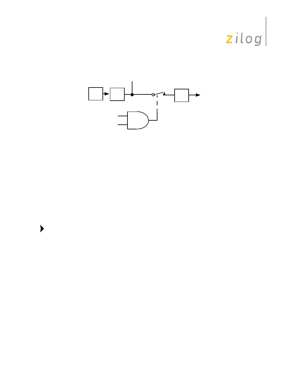
Figure 79. Internal Clock Output Through T
OUT
OSC
÷
2
P3
6
T
OUT
Internal
TMR D
6
Clock
TMR D
7
Note:
- Z86233 Z86243 Z86733 Z86743 Z86C02 Z86C04 Z86C08 Z86C15 Z86C21 Z86C30 Z86C31 Z86C33 Z86C36 Z86C40 Z86C43 Z86C61 Z86C62 Z86C63 Z86C65 Z86C83 Z86C90 Z86C91 Z86C93 Z86C96 Z86E02 Z86E03 Z86E04 Z86E06 Z86E07 Z86E08 Z86E15 Z86E21 Z86E30 Z86E31 Z86E33 Z86E34 Z86E40 Z86E43 Z86E44 Z86E61 Z86E63 Z86E83 Z86K15 Z86L02 Z86L04 Z86L08 Z86L16 Z8E000 Z8E001 Z8PE003