Page line 50 khz vlc transmission, Page line ground fault detection – GAI-Tronics LE300-IP Page/Party Line Extender User Manual
Page 12
Pub. 42004-488C
M
ODEL
LE300-IP
P
AGE
/P
ARTY
®
L
INE
E
XTENDER
P
AGE
9 of 68
e:\standard ioms - current release\42004 instr. manuals\42004-488c.doc
09/14
Page Line 50 kHz VLC Transmission
A pair of Model LE300-IP Line Extenders re-generates the 50 kHz VLC control signal between two
Page/Party
®
system cables. The 50 kHz VLC (Volume Level Control) signaling occurs on the page line
and is typically used to alter the speaker volume of Page/Party
®
stations equipped VLC receivers. VLC
signals may also be used for other on/off control functions on some Page/Party
®
systems. For proper
operation, both line extenders must have this feature enabled by setting DIP switch SW5 position 2. Refer
to Figure 6 for the location of switch SW5 on the Main PCBA and Table 6 below for setting options.
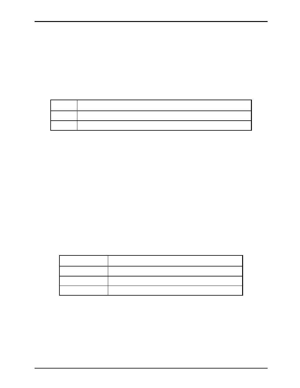
Table 6. Page Line 50 kHz VLC Transmission Setting on Main PCBA
SW5-2
Page Line 50 kHz VLC Transmission
Open*
50 kHz VLC is disabled.
Closed
50 kHz VLC is enabled.
N
OTES
: 1. Changes to this parameter take effect without cycling power.
2.
*Indicates
default
position.
N
OTE
: FSK operation and VLC operation (described above) cannot be enabled at the same time.
FSK operation is only used with SmartSeries systems.
VLC operation is only used within NON-SmartSeries systems. If both 50 kHz VLC and FSK are
enabled at the same time, neither feature will function correctly.
Page Line Ground Fault Detection
The Model LE300-IP Line Extenders provide page line ground fault detection on the local Page/Party
®
system cable. If multiple line extenders are connected to the same Page/Party
®
system cable segment, only
one page line ground fault detector may be enabled. A shorting clip setting at header P5 on the Main
PCBA enables the page line ground fault detection. Refer to Figure 6 for the location of header P5 on the
Main PCBA and Table 7 below for setting options:
Table 7. Page Line Ground Fault Detection Setting on Main PCBA
P5 Shorting Clip Page Line Ground Fault Detection
Pins 1–2*
Page line ground fault detection is disabled.
Pins 2–3
Page line ground fault detection is enabled.
Removed
Page line ground fault detection is disabled.
N
OTES
:
1. If connecting an LE300-IP Line Extender to the same system cable segment as an ADVANCE
Page/Party
®
Interface (PPI) card, disable the LE300-IP page line ground fault detector. The PPI card
contains the ground fault detector. If both ground fault circuits are enabled simultaneously,
intermittent SmartSeries FSK data errors will occur between the PPI card and SmartSeries stations.
2. Changes to this parameter take effect without cycling power.
3. *Indicates default position.