T1/e1 data line grounding, Lvds data link settings – GAI-Tronics LE300-IP Page/Party Line Extender User Manual
Page 23
Pub. 42004-488C
M
ODEL
LE300-IP
P
AGE
/P
ARTY
®
L
INE
E
XTENDER
P
AGE
20 of 68
e:\standard ioms - current release\42004 instr. manuals\42004-488c.doc
09/14
T1/E1 Data Line Grounding
T1/E1 data line can be floating or grounded. When floating, neither conductor of the data line cable pair is
connected to ground. Headers P20 and P21 control the grounding of the T1/E1 lines. Grounding the
T1/E1 lines may reduce emissions if it becomes an installation concern. Refer to Figure 6 for the location
of P20 and P21 on the Main PCBA and Table 21 below for setting details.
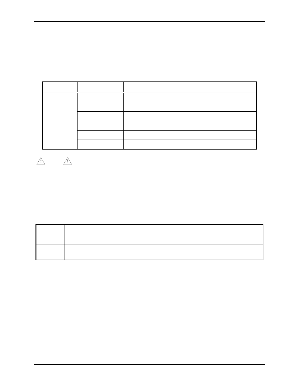
Table 21. T1/E1 Data Line Grounding setting on Main PCBA
Header
Shorting Clip
Grounding Condition
P20
1–2*
T1/E1 Rx line floating
2–3
T1/E1 Rx line grounded
Removed
T1/E1 Rx line floating
P21
1–2*
T1/E1 Tx line floating
2–3
T1/E1 Tx line grounded
Removed
T1/E1 Tx line floating
*Indicates default position.
NOTE
Do not ground the T1/E1 lines at both ends. Doing so will create a ground loop.
LVDS Data Link Settings
The LVDS “in” port is disabled unless it is receiving a signal from LVDS “out” from another line
extender. Switch SW3 position 3 enables the LVDS “in” port. Refer to Figure 6 for the location of SW3
on the Main PCBA and Table 22 below for setting details.
Table 22. LVDS “IN” Setting on Main PCBA
SW3-3
Enable/Disable LVDS “IN” Port
Open*
The LVDS “in” port is disabled (no cable connection from another LE300-IP.)
Closed
The LVDS “in” port is enabled (cable is connected to LVDS “out” cable connection
from anther to LVDS.
N
OTES
: 1. Changes to this parameter take effect after cycling power.
2.
*Indicates
default
position.