Page/party, Line balance – GAI-Tronics LE300-IP Page/Party Line Extender User Manual
Page 18
Pub. 42004-488C
M
ODEL
LE300-IP
P
AGE
/P
ARTY
®
L
INE
E
XTENDER
P
AGE
15 of 68
e:\standard ioms - current release\42004 instr. manuals\42004-488c.doc
09/14
Page/Party
®
Line Balance
For proper system operation, the page line and party lines 1 through 5 must be terminated with a resistance
of approximately 33 ohms. The Model LE300-IP provides potentiometers to set the line balance resistance
on the page line and five party lines. The line balance resistors are located on the Audio Termination
Connection Module next to the page and party line terminal blocks. The line balance resistors are
adjustable or can be disabled using shorting clips P1–P7.
If connecting an LE300-IP Line Extender to the same system cable segment as an ADVANCE Page/Party
®
Interface (PPI) card, disable the line balance for party lines 1, 2, and the page line. The PPI card provides
the line balance resistors for these audio lines. Refer to Figure 3 for the location of the Audio Termination
Connection Module. Refer to Figure 4 for the location of the jumpers and potentiometers on the Audio
Termination Connection Module and Table 15 below for setting details.
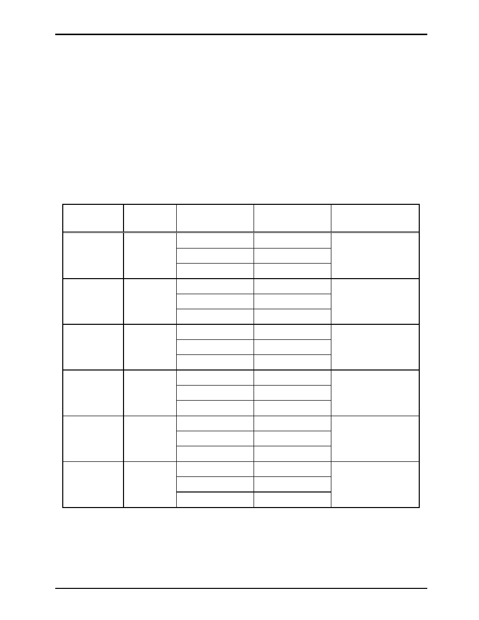
Table 15. Page/Party
®
Line Balance Settings on Audio Termination Connection Module
Audio Line
Header
Shorting Clip
Line Balance
Adjustment
Potentiometer
Party Line 5
P6
Pins 1–2*
Disabled
R23
Pins 2–3
Enabled
Removed Disabled
Party Line 4
P3
Pins 1–2*
Disabled
R19
Pins 2–3
Enabled
Removed Disabled
Party Line 3
P1
Pins 1–2*
Disabled
R3
Pins 2–3
Enabled
Removed Disabled
Party Line 2
P2
Pins 1–2*
Disabled
R4
Pins 2–3
Enabled
Removed Disabled
Party Line 1
P4
Pins 1–2*
Disabled
R20
Pins 2–3
Enabled
Removed Disabled
Page Line
P7
Pins 1–2*
Disabled
R24
Pins 2–3
Enabled
Removed Disabled
N
OTES
: *Indicates default position.