Contact closure inputs & relay outputs (i/o), Echo cancellation, Manual initiation of echo canceling – GAI-Tronics LE300-IP Page/Party Line Extender User Manual
Page 19
Pub. 42004-488C
M
ODEL
LE300-IP
P
AGE
/P
ARTY
®
L
INE
E
XTENDER
P
AGE
16 of 68
e:\standard ioms - current release\42004 instr. manuals\42004-488c.doc
09/14
Contact Closure Inputs & Relay Outputs (I/O)
Five independent contact closures can be transmitted across a pair of line extenders, meaning that an active
input contact on the local line extender results in the corresponding output relay contact energizing on the
remote line extender. Contact closures are bi-directional between line extender pairs.
Example: Closing a switch contact across input #1 of the local line extender results in relay output #1
activating on the remote line extender and vice versa. When the input contact is removed the
corresponding output relay de-activates. No switch or jumper setting is required on the Main PCBA for
configuring the I/O feature.
N
OTE
: Any active output contacts will deactivate if the data link is broken between the line extenders.
Echo Cancellation
Line echo (also known as electric or hybrid echo) is created by the electrical circuitry connected to a two-
wire (full duplex) audio system. Echo is inherent in all full-duplex audio systems and is affected by the
audio line length and line impedance mismatches. The presence of audible echoes results in undesirable
audio quality. This kind of quality degradation is inherent in network equipment and end-user telephone
devices.
To minimize echo, the Model LE300-IP performs an echo cancellation sequence on party lines 1 through
5. The echo cancellation process takes approximately 15 seconds and is performed automatically one
minute after power is applied to the LE300-IP. This delay allows all power levels to stabilize prior to
performing echo cancellation.
N
OTE
: Signal impulses are transmitted onto the party lines during the echo cancellation process. Handset
station users on a party line will hear the signals in the handset receiver. For troubleshooting purposes, the
1-minute delay may be disabled by closing DIP switch SW6 position 1. Refer to Figure 6 for the location
of SW6 on the Main PCBA and Table 16 below for setting details.
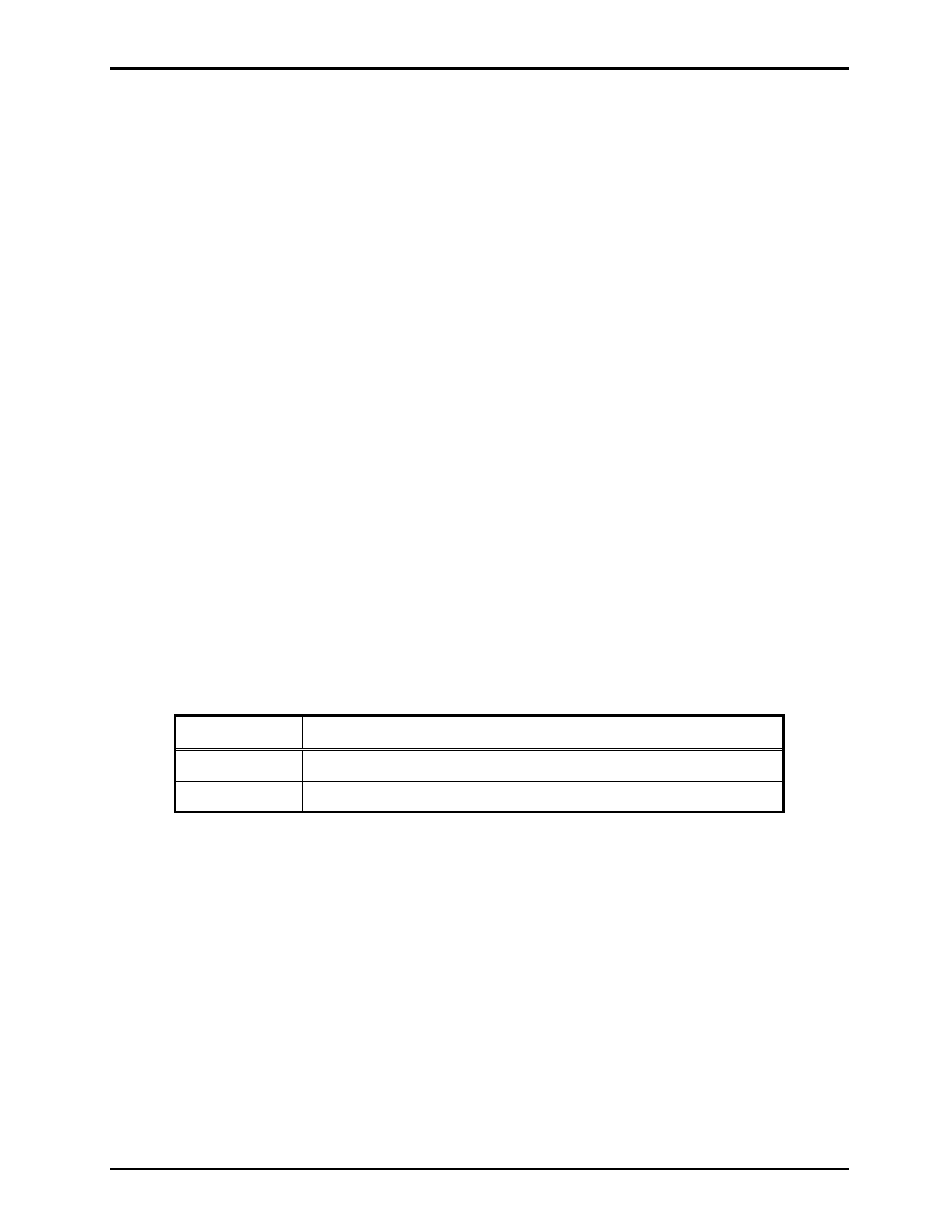
Table 16. Echo Cancellation Power-On Delay Setting on Main PCBA
SW6-1
Echo Cancellation Power-On Delay
Open* 1
minute
Closed No
delay
N
OTES
: 1. Changes to this parameter take effect when cycling power.
2. *Indicates default position.
Manual Initiation of Echo Canceling
Echo cancellation can be manually initiated as described below.
Press and release push button PB1 on the Main PCBA three times. The push button must be pressed for at
least 0.25 second and no more than 2 seconds each time. The timing requirement is meant to prevent
accidental requests. If an error is made with the push-button timing, the sequence must be repeated from
the beginning.
The LEDs on the Main PCBA will indicate the progress of the echo canceling sequence. One column of
LEDs turns on after each push button and press release until the sequence is started. Once the sequence is
started, those LEDs remain on, and a countdown timer is displayed on the remaining LEDs. The LEDs
turn OFF after the echo cancellation training sequence is complete.