Mcu connections, Electrical interface – GAI-Tronics ICP9000 Navigator Series Console Installation and Service Manual User Manual
Page 21
ICP9000 Navigator Installation and Service Manual
Installation
17
12/10
MCU Connections
The electrical hook-up of the ICP9000 Navigator MCU requires these basic connections: the ground wire,
one to three channel interface cables, and the power supply cable.
WARNING
Voltages hazardous to life may be present at the exposed control line terminals under certain conditions
during the following procedures. These voltages are also present on some component leads. Care should
be taken to avoid shock during installation.
Electrical Interface
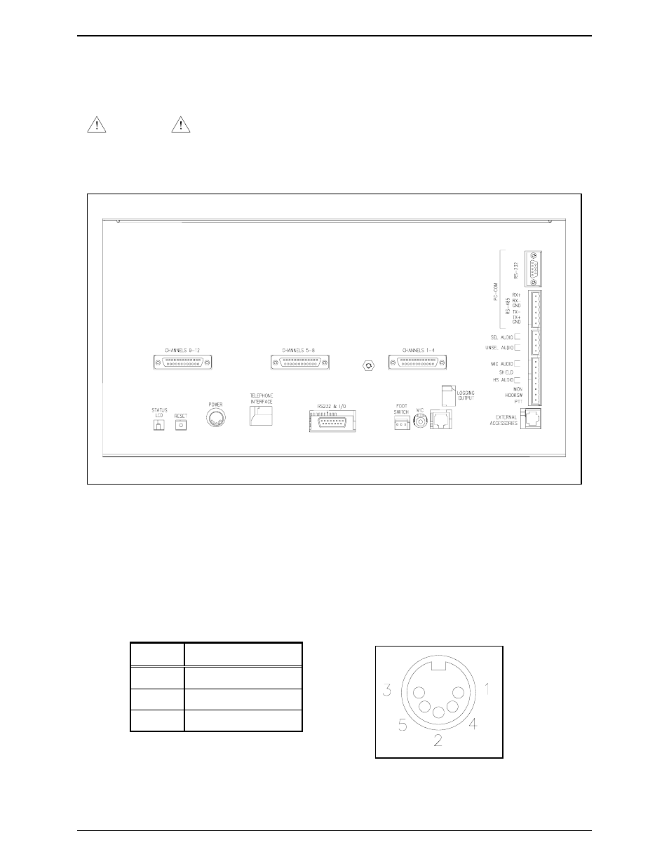
All of the electrical connections to the console are made at the rear panel. Power to the console is
furnished through a 5-pin, DIN connector, P5. The Figure 3 shows the rear view of the ICP9000
Navigator MCU and the locations of the various connectors. The pinout for the power DIN connector is
shown in Table 4:
Table 4. Power DIN Connector Pinout
Pins Function
1, 4
B-, Batt-, GND tab
3, 5
B+, IN
2 Batt+
Figure 4. Power Connector Pinout
Figure 3. View of ICP9000 Navigator MCU Back Panel with Connectors