Xcp0140a headset interface box, Handset/headset connector, Xdm003a desk mic/gooseneck mic – GAI-Tronics ICP9000 Navigator Series Console Installation and Service Manual User Manual
Page 28: Xfs002a footswitch
Installation
ICP9000 Navigator Installation and Service Manual
12/10 24
XCP0140A Headset Interface Box
The interface box allows the use of several headset accessories,
such as the Startset II, Supra headband-style monaural headset, and
Supra headband-style noise-canceling headset. The headset jack is
assembled for mounting beneath a horizontal surface or edge. Its
use requires proper jumper installation. See Figure 8 for jumper
locations.
If left-hand mounting is required, reverse the assembly. The
headset plugs into the modular-style headset jack (located directly
beneath the Logging Output jack) on the rear panel of the MCU.
See Table 9 for the headset modular jack pinout.
1. Remove the Navigator control ribbon cable from PP1 on the
Navigator Display Extender PC board and PP1 on the main
board. Keep the cable for future use. Use Figure 8 for
reference on the main board.
2. Position the shorting clip from PP1 to PP2 to enable operation of the headset. This option must
also be enabled and the sensitivity of the headset microphone set in the User Parameters Menu as
described in the Console Diagnostics section. Refer to Table 9 for the headset jack pinout.
Handset/Headset Connector
An 8-pin modular connector is provided for direct connection of
the XCP0500A Desktop Handset or the XDM002A Microphone.
(The XDM002A is not recommended for console operation.)
No jumper settings are required.
XDM003A Desk Mic/Gooseneck Mic
This heavy-duty desktop/gooseneck microphone connects
directly to the RCA connector labeled
MIC
located on the rear
panel of the MCU via the 61531-028 microphone extension
cable (12 feet in length) packaged with the Navigator. No
jumper settings are required.
XFS002A Footswitch
This accessory, which provides both hands-free PTT and
monitor functions, is provided with a cable fitted with a keyed
connector containing three contacts. This connector mates with
P7 on the back of the MCU. Table 11 defines the function of each pin.
NOTE
If the desk mic or footswitch is connected after the MCU has
been powered up, the MCU must be powered down and
powered up again. This allows the MCU to read the polarity
of the monitor switch. DO NOT press the monitor switch
while the console is powering up, or the polarity will be read
incorrectly.
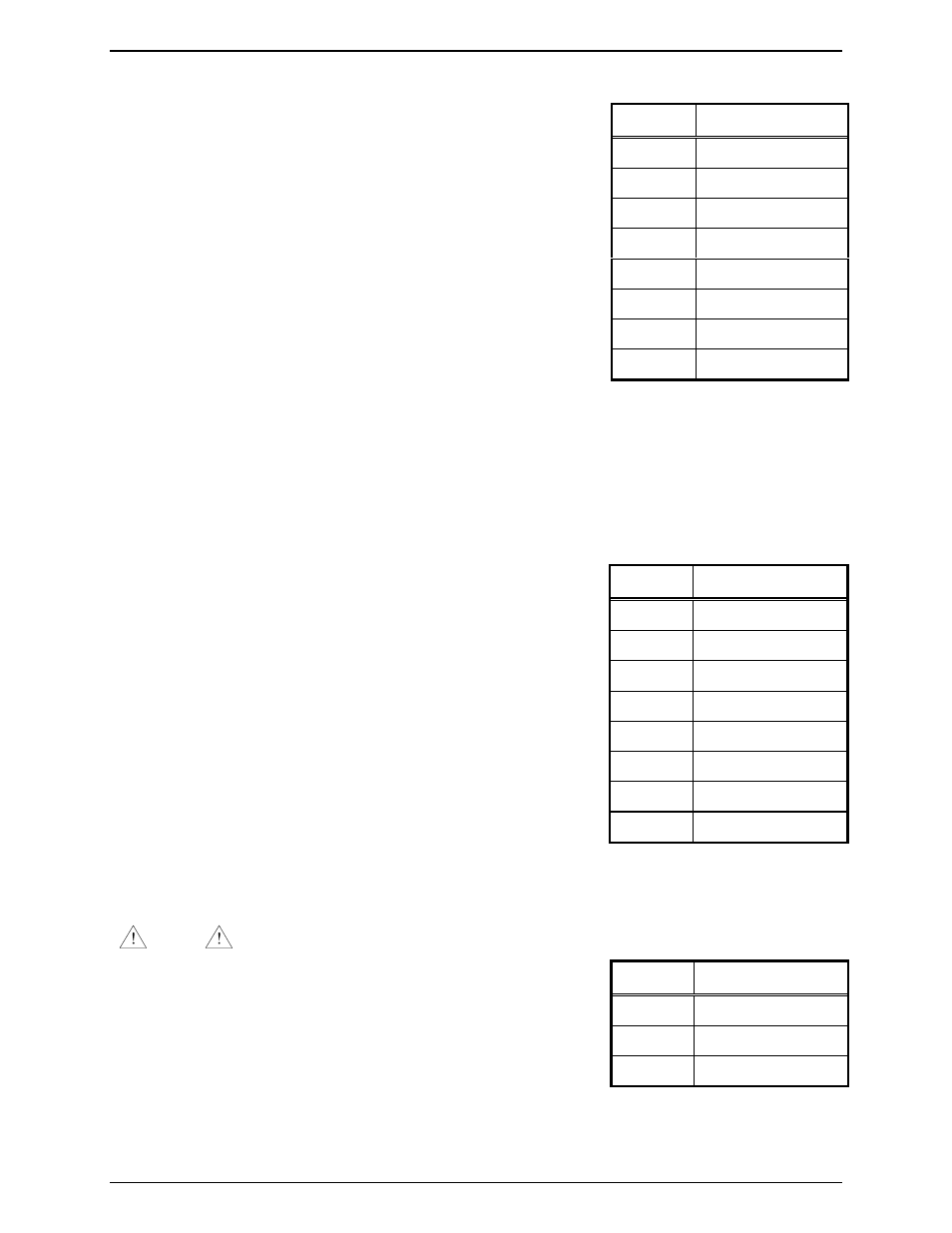
Table 9. Headset Modular Jack
Pin No. Pin Function
1 TX
Lo
2 TX
Hi
3 PTT
4 On-hook
5 GND
6 RX
Audio
7 PTT
Return
8 N/C
Table 10. Desk Mic Connector
Pinout
Pin No. Pin Function
1 Logic
GND
2 RS-232
Host
TX
3 PTT
4 Mic
Hi
5 Mic
Lo
6 Monitor
7
RS-232 Host RX
8
10 V dc
Table 11. Footswitch Connector Pinout
Pin No. Pin Function
1 PTT
2 GND
3 Monitor