Channel e&m control cp0040/xcp0040a – GAI-Tronics ICP9000 Navigator Series Console Installation and Service Manual User Manual
Page 58
Features and Options
ICP9000 Navigator Installation and Service Manual
12/10 54
4-Channel E&M Control CP0040/XCP0040A
The 4-Channel E&M Control Option consists of an additional board that must be installed into the
required supervisor option CP0050/XCP0050A of the MCU. This option adds E&M control in groups of
four channels, up to 12 channels, to the console.
In addition to the transmit and receive audio lines, E&M control uses two pairs of leads, M-lead pair and
E-Lead pair, to provide control between the console and the base station. The connection to the
transmitter should include the transmitter’s M-lead input and the transmitter’s common (positive or
negative ground). Polarity of the M-lead pair is not important as each M-lead pair is implemented with a
solid-state relay which provides a contact closure between the pair and provides up to 4000 V
RMS
isolation
between the console and the transmitter. The M-lead can switch up to 350 V dc at 130 mA continuous.
The E-lead connection to the receiver should include the receiver’s E-lead output and the receiver’s
common (positive or negative ground). The console’s E-lead is asserted when an approximate 0.6 V dc
or greater differential is applied across the E-lead pair. Polarity of the E-Lead pair is not important as the
E-lead is implemented using a bi-directional optocoupler providing 5000 V
RMS
isolation. Each E-lead
input can tolerate up to 50 V differential across the input pair.
If supervisor control of parallel consoles is required, the E&M output lines from those consoles should be
plugged directly into the
CONSOLE
connection of the E&M supervisor option. This ensures that parallel
consoles are not able to transmit on supervised channels.
To ensure that transmit audio from parallel consoles is also supervised, the landline audio connections
from the console to be supervised should be connected to the
FROM
PARALLEL
CONSOLE
on the E&M
supervisor option as well. The supervisor M-lead input is also implemented using a solid state relay that
maintains the necessary isolation.
Refer to the CARD Suite Software for details on configuring E&M control and supervisor control when
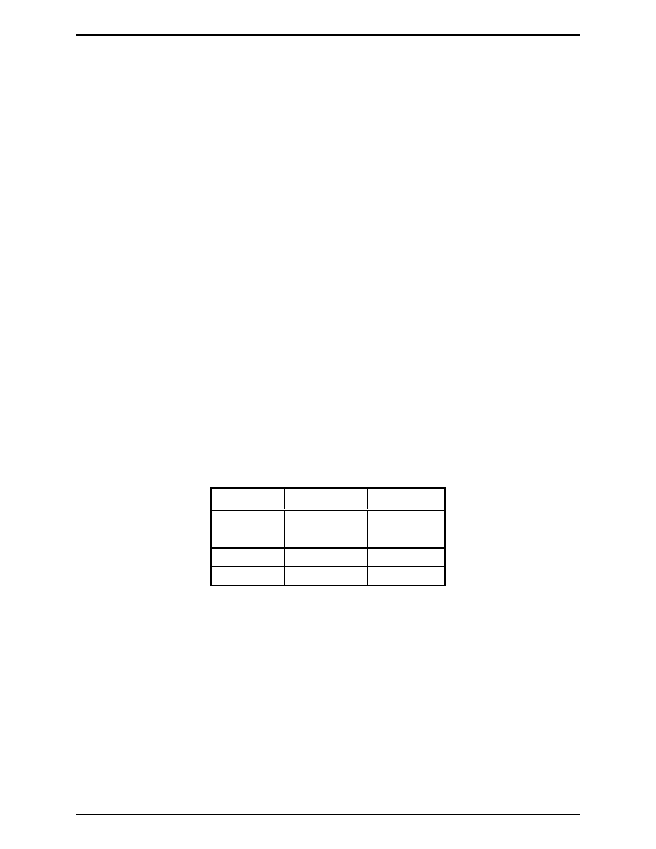
installing this option. Refer to Table 17 for the pinout of the E&M connectors as seen in Figure 31.
Table 17. Radio E& M Connections
Channel M-Lead E-Lead
1
6 & 5
16 & 15
2
8 & 7
14 & 13
3
10 & 9
4 & 3
4
12 & 11
2 & 1
The mating connector for the E&M connection is the same style as used to mate with a Motorola GM300
radio. The AMP Part No. is 104422-1 and should be available through most radio dealers.