Logging recorder output module, Dc control cp0010/xcp0010a, Installation/relocation – GAI-Tronics ICP9000 Navigator Series Console Installation and Service Manual User Manual
Page 56
Features and Options
ICP9000 Navigator Installation and Service Manual
12/10 52
Logging Recorder Output Module
This standard feature consists of an additional board that is installed in the ICP9000 Navigator MCU.
This feature adds a logging recorder output that provides a line-level sum of the transmit mic audio,
paging tones, receive audio, parallel console audio, and all signaling. This 600-ohm balanced output
should be connected to a suitable logging recorder to record all audio activity taking place on the console.
Refer to Figure 3 in this manual for the Logging Output connector location on the rear panel.
N
OTE
: The signaling control/module and the logging recorder output module are mutually exclusive. If
signaling control is required, the logging recorder module must be removed because they both occupy the
same board location. These two features can not co-exist.
DC Control CP0010/XCP0010A
This option provides standard dc control currents on a per channel basis. Its operation requires the
installation of one CDC card for each dc-controlled channel.
Installation/Relocation
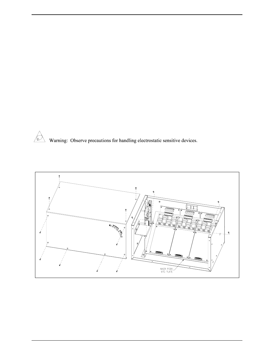
1. Disconnect power from the ICP9000 Navigator MCU.
2. Remove the ten screws securing the side cover panel and gently lift the cover. See Figure 28 below.
3. Disconnect all plugs attached to the inner slave board mounting plate. See Figure 28. Then remove
the four screws attaching the mounting plate to the main enclosure. This allows you to remove the
mounting plate.
Figure 28.