Printer interface, Installation – GAI-Tronics ICP9000 Navigator Series Console Installation and Service Manual User Manual
Page 55
ICP9000 Navigator Installation and Service Manual
Features and Options
51
12/10
Printer Interface
The Printer feature, when enabled through the CARD Suite Software, allows a printed log of receive
DTMF decode and signaling information to be captured. Optionally, an application such as Windows
HyperTeminal may be used on the Navigator PC to capture this data.
NOTE
The printer feature requires the use of a serial printer. A parallel printer output
is not available.
Installation
1. Use the CARD Suite Software application to configure the console. The Printer Installed selection
(Console Parameters tab) must be enabled. Select the desired Printer Incoming Messages and Printer
Outgoing Messages on the Digital Signaling Console Parameters tab.
2. After programming has been completed, disconnect the programming cable from the RS-232 port.
3. Attach a customer-provided 25-pin serial interface (DB25) from the printer interface cable to the
printer and the 15-pin interface to the RS-232 & I/O connector on the MCU. Secure the plug screws
on each interface. Refer to the printer’s instruction manual for information concerning printer use.
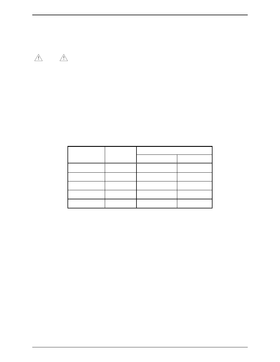
Table 15.
Connect to:
Pin
Description
Navigator DB25 (Printer)
DB9 (PC)
Ground 9 7 5
TX Data
10
3
2
RX Data
11
2
3
DSR 13
11
4
DTR 14
6
6
The following cables are available:
• Model XCP0170A – connects from the MCU’s RS-232 and I/O connector to the PC’s RS-232 port
(DB9). This cable is also used to program the MCU with the CARD Suite Software application.
• Model CP-SPTR-CBL – this is a serial printer cable that connects from the MCU’s RS-232 and I/O
connector to the printer’s 25-pin serial port.