Channel interface cable – GAI-Tronics ICP9000 Navigator Series Console Installation and Service Manual User Manual
Page 26
Installation
ICP9000 Navigator Installation and Service Manual
12/10 22
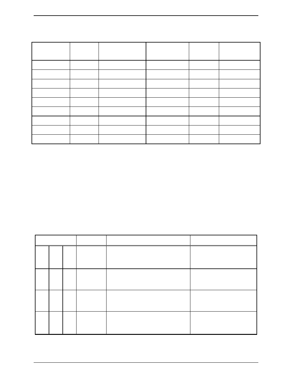
RS-485 Cable for Navigator MCU to Edgeport USB Converter
Table 7. Wiring Diagram
Edgeport
Connector
Pin
Number
Description
Navigator
Connector (TB1)
Pin
Number
Description
DB-9 female
1
No connection
DB-9 female
2
No connection
DB-9 female
3
TX Data Neg. (−) 6-pin
Phoenix
2
RX
−
DB-9 female
4
RX Data Pos. (+)
6-pin Phoenix
5
TX +
DB-9 female
5
Signal ground
6-pin Phoenix
3 & 6
GND
DB-9 female
6
No connection
DB-9 female
7
TX Data Pos. (+)
6-pin Phoenix
1
RX +
DB-9 female
8
RX Data Neg. (−) 6-pin
Phoenix
4
TX
−
DB-9 female
9
No connection
•
Pins 3 and 6 can be jumpered together on the Navigator 6-pin connector and one of these pins runs to
the DB-9 connector.
•
Set the individual switches of the 8-position switch on the Edgeport/2i as follows:
Starting with switch 1: D, D, D, D, U, U, X, X (D = down; U = up; X = doesn’t matter)
Channel Interface Cable
A 12-pair interface cable (one supplied for each four channels of operation) plugs into the 25-pin
D-connectors on the back of the console. Refer to Figure 3 showing the rear view of the console. The
ICP9004A 4-channel console employs only one 25-pin D-connector-cable assembly for connections to
the base station(s) control and audio pairs, generally through a termination block or connector. Refer to
Table 8 for wire colors and pin functions.
Table 8. Channel Interface Connectors and Cable Colors
Channel No.
Pin No.
Wire Colors
Pin Function
1 5 9
14
15
1, 2
White/blue
Blue/white
White/orange, Orange/white
TX Audio + /RX 2-Wire
TX Audio – /RX 2-Wire
RX Audio 4-Wire
2 6 10
3
4
5, 6
White/green
Green/white
White/brown, Brown/white
TX Audio + /RX 2-Wire
TX Audio – /RX 2-Wire
RX Audio 4-Wire
3 7 11
8
9
10, 11
White/gray
Gray/white
Red/blue, Blue/red
TX Audio + /RX 2-Wire
TX Audio – /RX 2-Wire
RX Audio 4-Wire
4 8 12
12
13
24, 25
Red/orange
Orange/red
Red/green, Green/red
TX Audio + /RX 2-Wire
TX Audio – /RX 2-Wire
RX Audio 4-Wire
Some installations can use the optional XCP0030A 25-pair Telco Interface Option Field Installation Kit,
when the telephone company supplies a 50-pin standard USOC, RJ21X Telephone Connector.