Pair telco interface xcp0030a, Installation, Rear panel mounting – GAI-Tronics ICP9000 Navigator Series Console Installation and Service Manual User Manual
Page 61
ICP9000 Navigator Installation and Service Manual
Features and Options
57
12/10
25-Pair Telco Interface XCP0030A
The Telco Interface Kit adapts the DB25 rear panel connectors to a single 50-pin standard connector
USOCK designated RJ27X. The unit mounts on the rear panel of the ICP9000 Navigator MCU and plugs
into the three DB25 connectors, P40 (a) (b) (c). The Model XCP0030A 25-Pair Telco Interface Kit
includes the following components:
Qty Description
1
Telco Interface Adapter
2
6-32
× 1.625 screws
Installation
Rear Panel Mounting
1. Disconnect the power from the ICP9000 Navigator MCU and remove all attached cables from the
rear cover. Remove stand-offs.
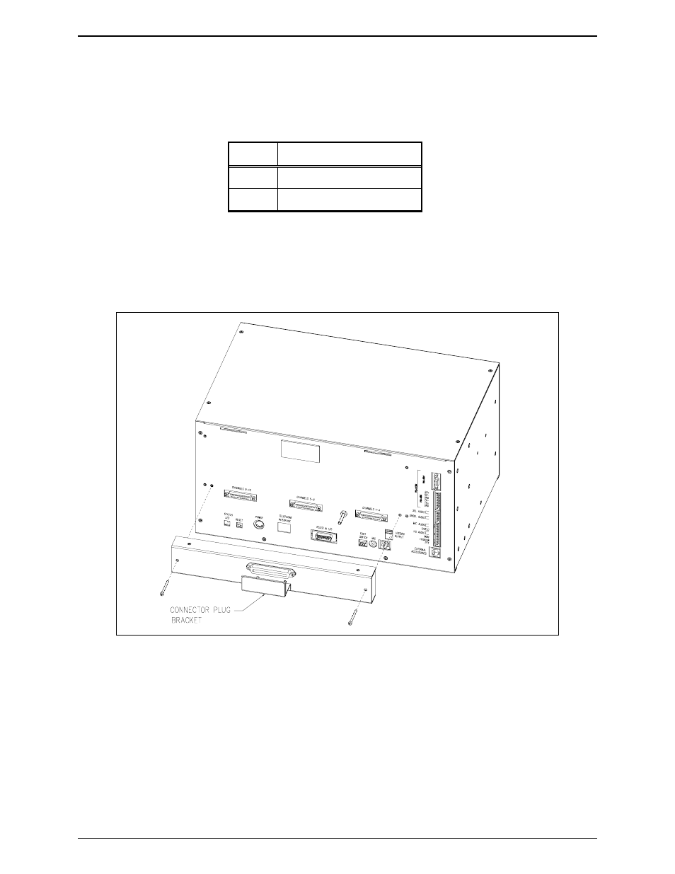
2. Mount the Telco Interface to the rear of the MCU. Refer to Figure 30. Position the Telco Interface
so that the three DB25 connector plugs line up with the DB25 connector receptacles on the rear panel.
3. Secure the Telco Interface with the supplied #6-32 screws shown in Figure 30, tightening them until
the Telco unit is snug against the rear panel.
4. Plug one end of a standard RJ27X connector into the XCP0030A receptacle and terminate the other
end to an applicable punch block. Mount the connector plug bracket over the 50-pin connector and
secure with two screws. The bracket secures the connector to the Telco interface.
5. Reattach all other cables and reconnect the power.
Figure 30.