22 video – LSC Lighting maXim MP User Manual
Page 73
maXim
MP L(P) XL(P) XXL(P)
Operator Manual V3
LSC Lighting Systems (Aust) Pty. Ltd.
Page 67
22 VIDEO
22.1 VIDEO
OVERVIEW
Your maXim is fitted with a VIDEO output to connect a SVGA computer monitor.
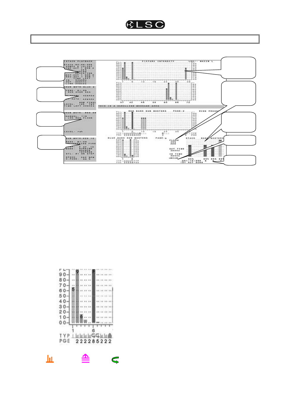
Typical video screen.
The video screen is divided into the main display
(the white area on this simulation) and the
selectable areas
(dark areas on the left).
22.2 MAIN
DISPLAY
The main part of the screen shows the fixture
intensities (cyan bargraphs) at the top, a message
area in the middle and the status of the playbacks,
flash settings, time masters, STL settings, USB
devices, stack and masters at the bottom.
Intensity levels are shown in tens on the side axis
of the display and in units inside each individual
bar. The “Fixture Intensity” levels are shown prior
to the patch.
The contents of each playback is shown in the
“TYP” (TYPE) row by a symbol and colour. The
colour is repeated in the bargraph.
Scene
Stack
Chase
In this example;
• Playbacks 2, 3, 4, 5, 8 & 9 contain
scenes
(orange).
• Playback 6 and 7 contain chases (green).
• Playback 10 is a stack memory
(magenta).
The page number that the memory is recorded
in is shown in the “PGE” (PAGE) row. This
may be different to the current page due to a
“page freeze”. In this example, playbacks 6
and 7 contain chases from pages 8 and 5
respectively.
22.3 SELECTABLE
AREAS
The left side of the screen is selected by the
operator and shows either:
• 1 of 4 selectable video pages (not shown
above, see below) or
• If none of the 4 pages are selected it further
divides the left side into 4 areas and allows
you to select any 4 Playbacks or the stack
master and “pin” a status display for that
Playback or stack into any of the 4 positions
(as shown above).
22.3.1 PINNED
VIDEO
When a playback or the stack is “selected’, a
video display is automatically pinned. Press;
[select], [f/a] (playback or stack to pin).
To select a specific position for the pinned display;
HOLD
[function], tap [f/a] (video 1 to 4).
(Video 1 is at the top left of the screen and video 4
is at the bottom).
Holding
[function] and tapping [f/a] (video 1 to 4)
again, turns off (unpins) the display.
Press [select] (de-selects select) to finish.
Bargraphs of
fixture output
levels.
“Pinned”
video 1
“Pinned”
video 4
Playback &
Masters
status
“Pinned”
video 3
“Pinned”
video 2
Flash, Time
fader and
STL settings.
USB status
MIDI status