Vcm-x component & systems wiring 117, Warning – Orion System VCM-X E-BUS Component User Manual
Page 117
VCM-X Component & Systems Wiring
117
Miscellaneous Diagrams and Technical Information
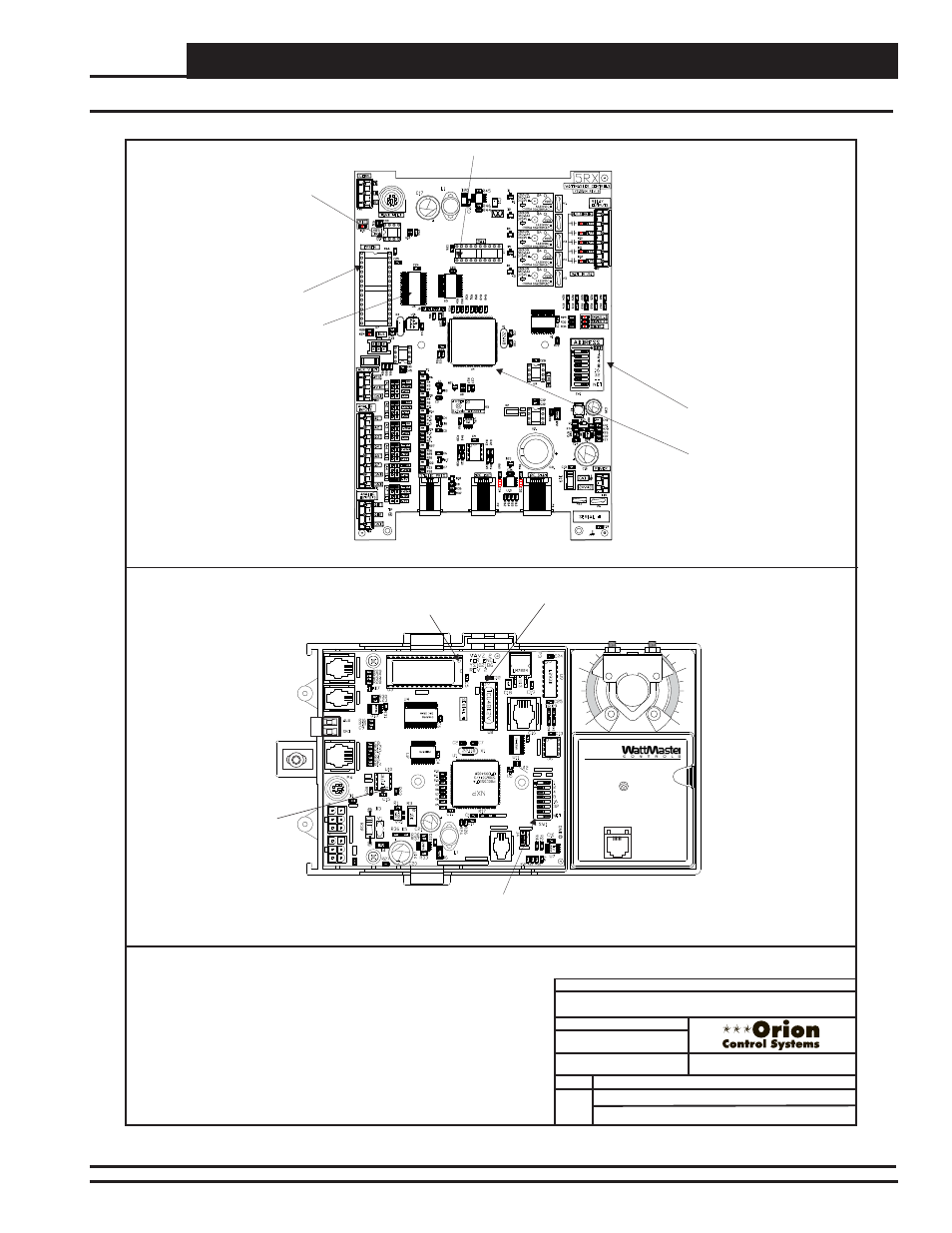
EPROM Chip Locations
RAM Chip
(U6) Pin 1
EPROM Chip
(U7) Pin 1
PAL Chip
(U10) Pin 1
RS-485
Communications
Driver Chip
(U14) Pin 1
Address Switch
CPU (U4)
FILENAME
DATE:
B. CREWS
DESCRIPTION:
PAGE
DRAWN BY:
JOB NAME
1 of 4
E
X
PAN
S
ION
D
'S
TAT
S
PACE
SENSOR
POWER
/
C
O
M
M
ST
A
T
MADE IN USA
WATTMASTER CONTROLS INC
HI(VAV)
LOW(VVT)
VE
L
O
C
IT
Y
ADDRESS
OFF
ON
EPROM
PAL
485
REC
DRV
EE
PR
O
M
93C66
AC
TU
ATO
R
1
0
OE282
AIRFLOW
WDOG
24
Mhz
PROCESSO
R
PWR
RAM Chip
(U8) Pin 1
EPROM Chip
(U3) Pin 1
Communications
Driver Chip
(U10) Pin 1
Address Switch
OE742-31-VAVZ or OE742-31-VAVZ VAV/Zone Controller Actuator Package
OE332-23E-VCMX-MOD - VCM-X E-BUS Controller
O-VCMX-DRCHPREP-1B.CDR
Product Chip Replacement Information
Orion Components VCM-X
10/09/09
Warning!
Use Extreme Caution When Removing Any Chips To Avoid
Damaging Any Circuit Board Traces Which Are Under The Chip.
Be Sure That Any Small Screwdriver Or Other Sharp Object Used
To Remove The Chip Does Not Come Into Contact With The Printed
Circuit Board.
A Small Screwdriver May Be Inserted Between The Chip And The
Socket To Aid In Removal Of The Chip.
Be Very Careful Not To Insert The Screwdriver Under The
Socket!! Damage To The Board Is Not Covered By Warranty.
DATE:
S. OLSON
BY:
05/20/15
Figure 91: EPROM Chip Locations for VCM-X E-BUS & VAV/Zone Controller Actuator Package