Communication devices, On-site computer connections & wiring, Vcm-x component & systems wiring 78 – Orion System VCM-X E-BUS Component User Manual
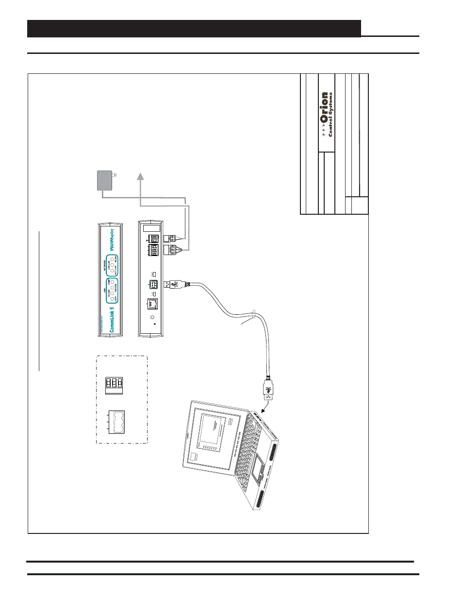
Page 78: Optional computer connection diagram, Figure 56: on-site computer connection, Front v iew) commlink 5, Back v iew) commlink 5
VCM-X Component & Systems Wiring
78
Communication Devices
USB Cable
Assembly
(Supplied W
ith CommLink 5)
T
ype
A
USB
Cable End
T
ype B USB
Cable End
Job-Site Laptop Computer
(By Others) with Prism 2 Software Installed
1
10 V
AC T
o
24 V
A
C
Power Pack
(Supplied W
ith CommLink 5)
Connect
T
o
MiniLink PD Network
T
erminals
(When Used)
Otherwise Connect to VCM-X E-BUS Controller
Communications
T
erminal
SHLD
T
R
T
ypical T
erminal Blocks.
All W
iring T
o
Be
T T
o
T
, SHLD (G) T
o
SHLD (G) & R T
o
R
T
G
R
485 LOOP
Connect
T
ype
A
Cable
End
T
o
USB Port On Desktop Or
Laptop Personal Computer &
T
ype B
End
T
o
USB Port On CommLink 5.
USB Drivers Supplied With
The
CommLink 5 Must
Be Installed On
Y
our Computer Before
The CommLink 5 Can
Be Used
NOTE:
FILENAME
DA
TE:
S. Olson
DESCRIPTION:
P
AGE
BY
:
Wiring & Connection Diagram
JOB NAME
1 of 1
Note:
Set CommLink Internal Switch
T
o
“Multi”
When
MiniLink PD Is Used Otherwise Switch Must Be Set
T
o
“Single”
Optional Computer Connection Diagram
O-VCMX-JS-Comp-Only-1A.cdr
VCM-X Job Site Computer Only
01/04/13
(Front V
iew)
CommLink 5
Serial #
COMPUTER
USB
10/100
ETHERNET
DIAG
485 LOOP
POWER
ACT
LNK
HIGH
LOW
BAUD
R(+)
24V
GND
SHLD
T(
-)
MULT
IPLE
SINGLE
LOOP
(Back V
iew)
CommLink 5
Figure 56: On-Site Computer Connection
On-Site Computer Connections & Wiring