System installation, Vcm-x component & systems wiring 9 – Orion System VCM-X E-BUS Component User Manual
Page 9
VCM-X Component & Systems Wiring
9
System Installation
FILENAME
DATE:
DESCRIPTION:
PAGE
Wire & Transformer Sizing
JOB NAME
O-VCMXWRSIZ1A.CDR
Orion VCM-X System
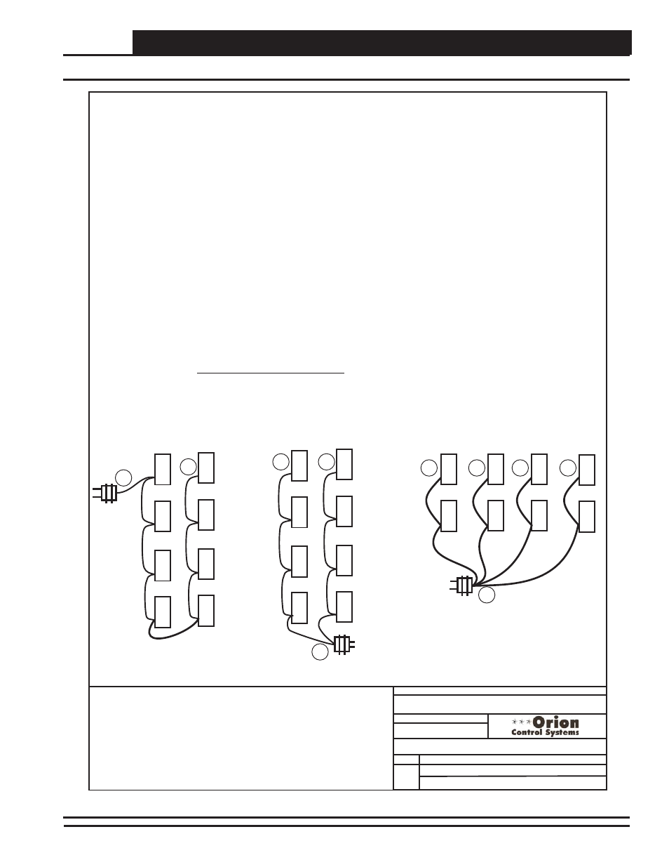
24 VAC Power - Transformer & Wire Sizing Considerations for Devices Without Modular Connectors
Component Power Requirements
120 / 24VAC
120 / 24VAC
Distance A to B cannot exceed 57.80 Ft.
Distance from A to B cannot exceed 115.60 Ft.
Distance from A to C cannot exceed 115.60 Ft.
Distance from A to B cannot exceed 230.40 Ft.
Distance from A to C cannot exceed
Ft.
Distance from A to D cannot exceed
Ft.
Distance from A to E cannot exceed
Ft.
230.40
230.40
230.40
120 / 24VAC
Some installers like to use one large 24 VAC transformer to power several devices. This is allowable as long as polarity is maintained to each device
on the transformer circuit.
Using
separate transformers also allows redundancy in case of a transformer failure. Instead of having 8 controllers inoperative because of a malfunctioning
transformer you have only 1 controller off line. If the installer does decide to use a large transformer to supply power to several devices, the following
transformer and wire sizing information is presented to help the installer correctly supply 24 VAC power to the devices.
Following is a typical example to help the installer to correctly evaluate transformer and wiring designs.
Each GPC-XP Controller requires 8 VA @ 24VAC power. In the examples below we have a total of 8 GPC-XP Controllers.
8 GPC-XP Controllers @ 8 VA each................ 8 x 8 VA = 64 VA.
The above calculation determines that our transformer will need to be sized for a minimum of 64 VA if we are to use one transformer to power all the
controllers.
Next we must determine the maximum length of run allowable for the wire gauge we wish to use in the installation. Each wire gauge below has a
voltage drop per foot value we use to calculate total voltage drop.
18ga wire.................................0.00054 = voltage drop per 1’ length of wire
16ga wire.................................0.00034 = voltage drop per 1’ length of wire
14ga wire.................................0.00021 = voltage drop per 1’ length of wire
For our example we will use 18 gauge wire. WattMaster recommends 18 gauge as a minimum wire size for all power wiring.
Next use the voltage drop per foot value for 18 gauge wire from the list above and multiply by the total VA load of the 8 controllers to be installed.
0.00054 (Voltage drop per foot for 18 gauge wire) x 64VA controller load =
Volts/Ft.
WattMaster controllers will operate efficiently with a voltage drop no greater than 2 Volts. Divide the total allowable voltage drop of 2 Volts by the
number you arrived at above and you have the maximum number of feet you can run the 18 gauge wire with an 75 VA transformer with no more than a
2 Volt drop at the farthest controller from the transformer..
2 (Volts total allowable voltage drop)
=
57.80
0.0346 (Voltage drop per 1 ft. @ 64VA load)
Parallel circuiting of the wiring instead of wiring all 8 controllers in series allows for longer wire runs to be used with the same size wire (as shown in
our examples below).
Warning:
If polarity is not maintained, severe damage to the devices may result. WattMaster Controls recommends
using a separate transformer for each device in order to eliminate the potential for damaging controllers due to incorrect polarity.
0.0346
feet
It is often necessary for the installer to calculate and weigh the cost and installation advantages and disadvantages of wire size,
transformer size, multiple transformers, circuiting, etc., when laying out an installation. No matter what layout scheme is decided upon, it is mandatory
that the farthest controller on the circuit is supplied with a minimum of 22 Volts.
GPC-X Controller ............................8 VA
VCM-X E-BUS Controller ................8 VA
GPC-XP Controller ..........................8 VA
Lighting Panel Controller .....10 VA
MiniLink Polling Device..........6 VA
A
A
A
B
C
D
E
B
B
C
1 of 2
01/07/13
VAV/Zone Controller.........................6 VA
Transformer Sizing & Wiring For Devices W/Out Modular Connectors
Figure 1: Transformer & Wire Sizing - Devices without Modular Connectors